System Bus Routing
R
72 Intel
®
Pentium
®
4 Processor / Intel
®
850 Chipset Family Platform Design Guide
5.4.1 Topologies
The following sections describe the topologies and layout recommendations for the miscellaneous
signals.
5.4.1.1 Topology 1: Asynchronous GTL+ Signals Driven by the Processor
These signals (FERR#, PROCHOT# and THERMTRIP#) should adhere to the following routing
and layout recommendations. Figure 34 and Figure 35 illustrate the recommended topologies. If
THERMTRIP# and PROCHOT# are routed to external logic, voltage translation may be required
to avoid excessive voltage levels at the processor and to meet input thresholds for the external
logic.
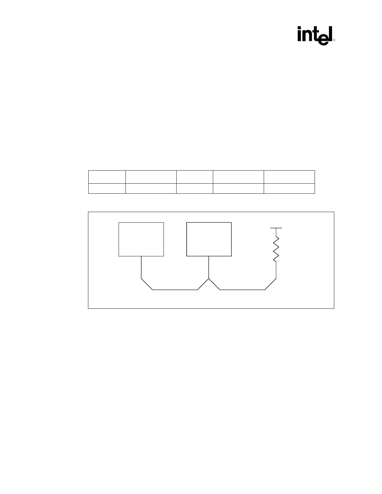
Table 14. Layout Recommendations for FERR# Signals (Topology 1a)
Trace Zo Trace Spacing L1 L3 Rpu
60 Ω 7 mil 1–12” 3” max 62 ±5% Ω
Figure 34. Routing Illustration for FERR#
Processor
Topo1_FERR_Route
R
PU
VCC_CPU
ICH2
L1 L3