Schematic Review Checklist
R
Intel
®
Pentium
®
4 Processor / Intel
®
850 Chipset Family Platform Design Guide 263
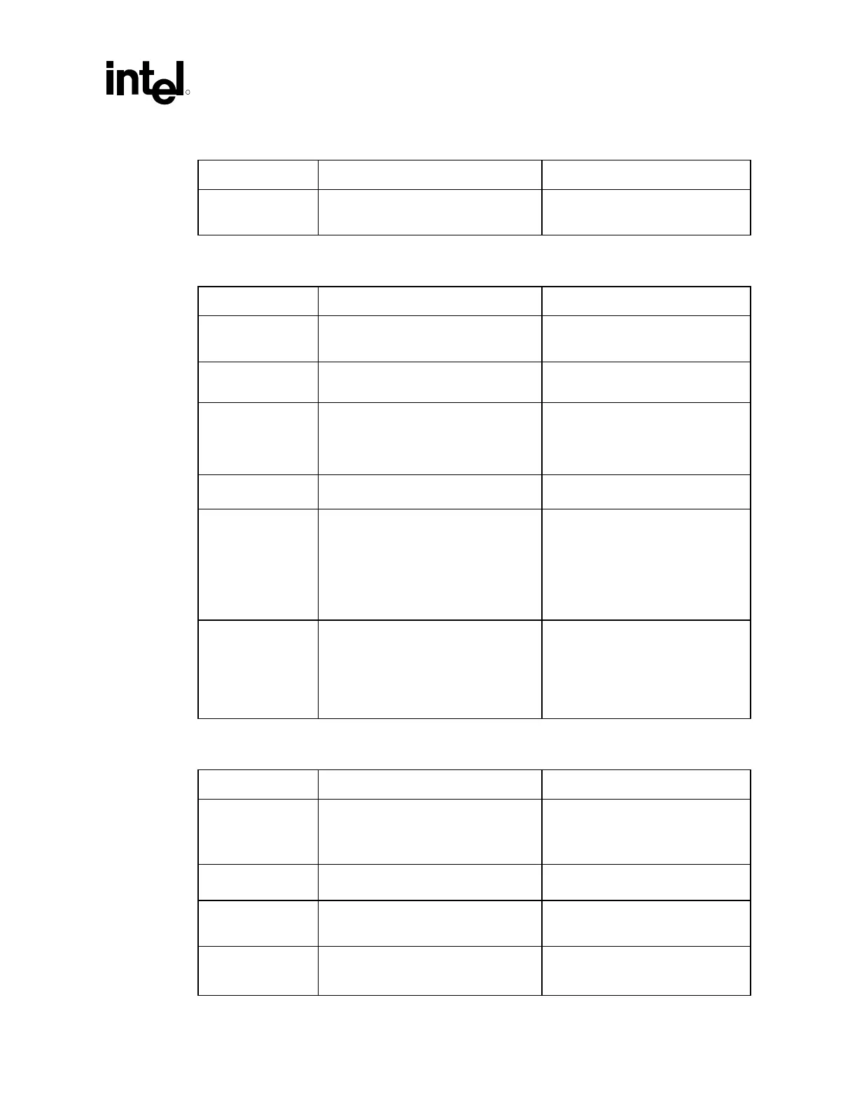
15.7.8 USB
Checklist Items Recommendations Reason/Impact
USBP[3:0]P
USBP[3:0]N
• See Section 9.4 for circuitry needed on
each differential Pair.
15.7.9 Power Management
Checklist Items Recommendations Reason/Impact
THRM# • Should not be used for this platform. A
pull-up is required on this signal.
• Input to ICH2 cannot float. THRM#
polarity bit defaults THRM# to
active low, so pull up.
SLP_S3#
SLP_S5#
• No pull-up/pull-down resistors needed.
Signals driven by ICH2.
• Signal driven by ICH2
PWROK • This signal should be connected to
power monitoring logic, and should go
high no sooner than 10 ms after both
VCC3_3 and VCC1_8 have reached
their nominal voltages
• Timing requirement
PWRBTN# • No extra pull-up resistors • These signals have integrated pull-
ups of 9 k
Ω ±3 kΩ.
RI# • RI# does not have an internal pull-up.
Recommend an 8.2 k
Ω pull-up resistor
to resume well
• If this signal is enabled as a wake
event, it is important to keep this
signal powered during the power
loss event. If this signal goes low
(active), when power returns, the
RI_STS bit will be set and the
system will interpret that as a wake
event.
RSMRST# • This signal should be connected to
power monitoring logic, and should go
high no sooner than 10 ms after both
VccSUS3_3 and VccSUS1_8 have
reached their nominal voltages. Can
be tied to RSMPWROK on desktop
platforms.
• Timing requirement
• Power-well Isolation
15.7.10 Processor Signals
Checklist Items Recommendations Reason/Impact
A20M#, CPUSLP#,
IGNNE#, INIT#,
INTR, NMI, SMI#,
STPCLK#
• Internal circuitry has been added to the
ICH2, external pull-up resistors are not
needed.
• Push/pull buffers now drive the
output signals.
FERR# • Terminate to VCC with a 62 Ω ±5%
resistor near the processor.
RCIN#
A20GATE
• Pull up signals to VCC3_3 through a
10 k
Ω resistor.
• Typically, driven by Open Drain
external microcontroller
CPUPWRGD • Connect to the processor’s
CPUPWRGD input. Requires weak
external pull-up resistor.
• Refer to processor documentation
of the processor that platform
utilizes for specific values.