Schematic Review Checklist
R
264 Intel
®
Pentium
®
4 Processor / Intel
®
850 Chipset Family Platform Design Guide
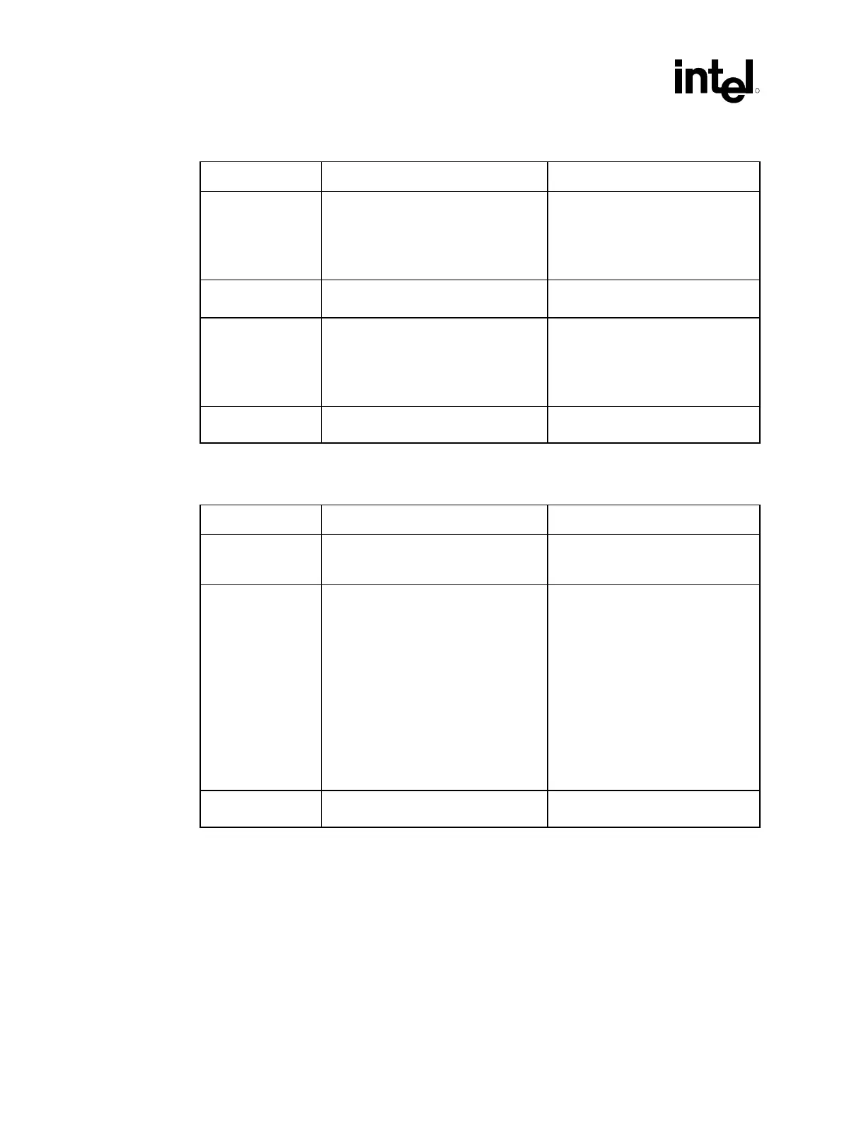
15.7.11 System Management
Checklist Items Recommendations Reason/Impact
SMBDATA
SMBCLK
• Requires external pull-up resistors.
See SMBus Architecture and Design
Consideration section to determine the
appropriate power well to use to tie the
pull-up resistors. (Core well, suspend
well, or a combination.)
• Value of pull-ups resistors
determined by line load. Typical
value used is 8.2 k
Ω.
SMBALERT#/
GPIO[11]
• See GPIO section if SMBALERT# not
implemented
SMLINK[1:0] • Requires external pull-up resistors.
See SMBus Architecture and Design
Consideration section to determine the
appropriate power well to use to tie the
pull-up resistors. (Core well, suspend
well, or a combination.)
• Value of pull-ups resistors
determined by line load. Typical
value used is 8.2 k
Ω.
INTRUDER# • Pull signal to V
CC
RTC (V
BAT
) if not
needed
• Signal in V
CC
RTC (V
BAT
) well
15.7.12 RTC
Checklist Items Recommendations Reason/Impact
VBIAS • The VBIAS pin of the ICH2 is
connected to a 0.047 µF capacitor.
See Section 9.8.7
• For noise immunity on VBIAS signal
RTCX1
RTCX2
• Connect a 32.768 kHz crystal oscillator
across these pins with a 10 M
Ω
resistor and use 12 pF decoupling
capacitors at each signal.
• RTCX1 can optionally be driven by an
external oscillator instead of a crystal.
These signals are 1.8 V only, and
must not be driven by a 3.3 V source.
• The ICH2 implements a new
internal oscillator circuit as
compared with the PIIX4 to reduce
power consumption. The external
circuitry shown in Section 9.7.1 will
be required to maintain the
accuracy of the RTC.
The circuitry is required since the
new RTC oscillator is sensitive to
step voltage changes in V
CCRTC
and
V
BIAS
. A negative step on power
supply of more than 100 mV will
temporarily shut off the oscillator for
hundreds of milliseconds.
SUSCLK • Route to Test Point if SUSCLK is
unused
• To assist in RTC circuit debug