I/O Controller Hub 2
R
186 Intel
®
Pentium
®
4 Processor / Intel
®
850 Chipset Family Platform Design Guide
9.12 Intel
®
ICH2 Decoupling Recommendations
The ICH2 is capable of generating large current swings when switching between logic high and
logic low. This condition could cause the component voltage rails to drop below specified limits.
To avoid this type of situation, ensure that the appropriate amount of bulk capacitance is added in
parallel to the voltage input pins. It is recommended that the developer use the amount of
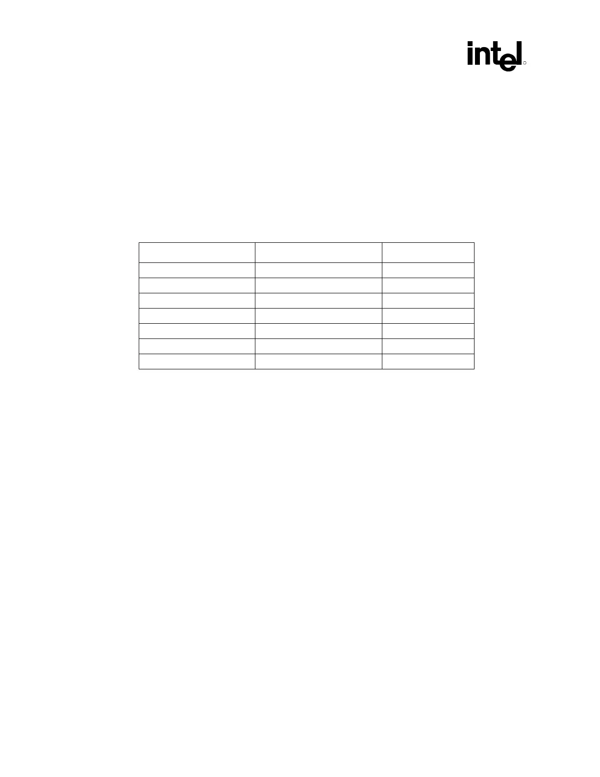
decoupling capacitors specified in Table 42 to ensure the component maintains stable supply
voltages. Also the capacitors should be placed as close to the package as possible. Maximum
distance allowed is 400 mils. It is recommended that the motherboard designer include pads for
extra decoupling capacitors should the recommendation not work on their board.
Table 42. Decoupling Capacitor Recommendation.
Power Plane # Decoupling Capacitors Capacitor Value
3.3 V Core 6 0.1 µF
3.3 V Stand By 1 0.1 µF
VCC_CPU 1 0.1 µF
1.8 V Core 2 0.1 µF
1.8 V Stand By 1 0.1 µF
5 V Reference 2 0.1 µF and 1 µF
5 V Reference Stand By 1 0.1 µF
9.13 Glue Chip 4 (Intel
®
ICH2 Glue Chip)
In order to reduce the component count and BOM cost of the Intel 850 chipset based-platform,
Intel has developed an ASIC component that integrates miscellaneous platform logic into a single
chip. The Glue Chip 4 is designed to integrate some or all of the following functions into a single
device. By integrating much of the required glue logic into a single device, overall board cost can
be reduced.
Glue Chip 4 Features:
• PWROK signal generation
• Control circuitry for Suspend To RAM
• Power Supply power up circuitry
• RSMRST# generation
• Backfeed cutoff circuit for Suspend to RAM
• 5 V reference generation
• Flash FLUSH# / INIT# circuit
• HD single color LED driver
• IDE reset signal generation/PCIRST# buffers
• Voltage translation for Audio MIDI signal
• Audio-disable circuit
• Voltage translation for DDC to monitor
• Tri-state buffers for test
More information regarding this component is available from your field representative