Hub Interface Routing
R
Intel
®
Pentium
®
4 Processor / Intel
®
850 Chipset Family Platform Design Guide 129
The reference voltage generated by a single HIREF divider should be bypassed to ground at each
component with a 0.01µF capacitor located close to the component HUBREF pin. If the reference
voltage is generated locally, the bypass capacitor needs to be close to the component HUBREF
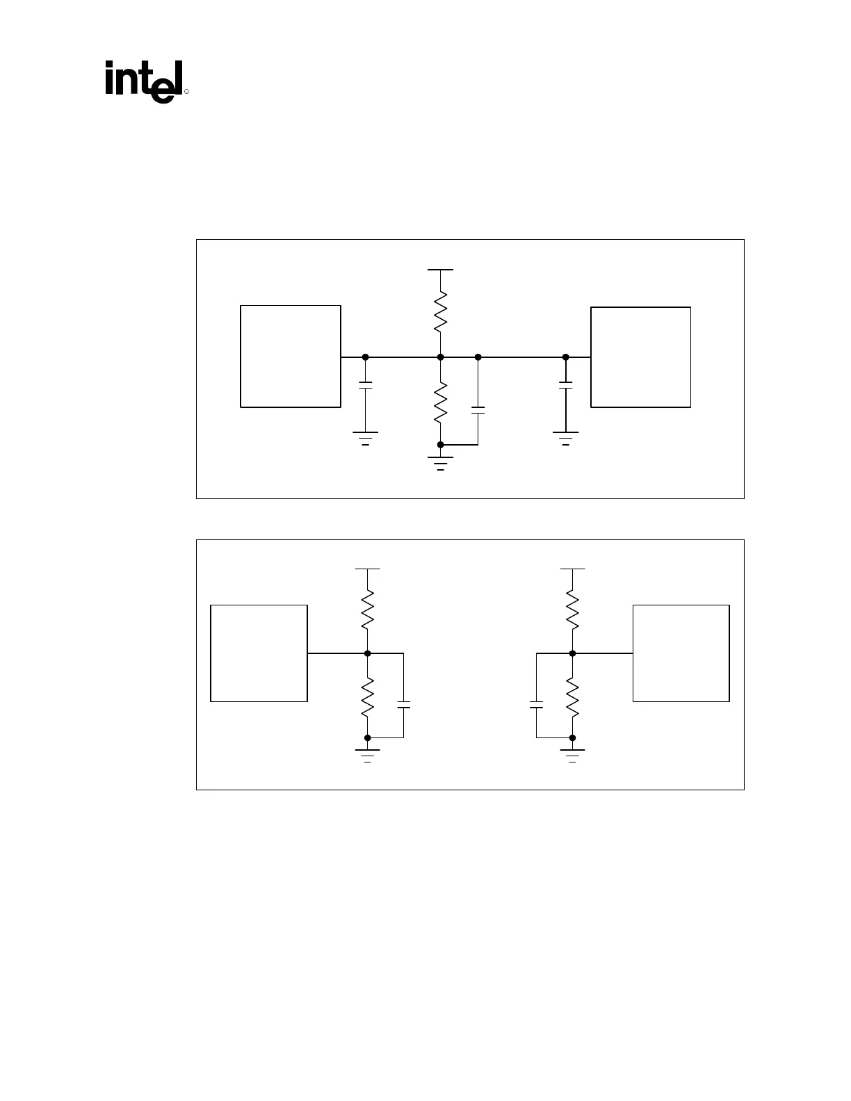
pin. Example HIREF divider circuits are shown in Figure 84 and Figure 85.
Figure 84. 8-Bit Hub Interface with a Shared Reference Divider Circuit (Normal Mode)
HLREF_A
HUBREF
MCH
ICH2
HubRef1
R1
1.8 V
R2
C2
C2
C1
Figure 85. 8-Bit Hub Interface with Locally Generated Reference Divider Circuits
HUBREF
HUBREF
MCH
ICH2
HubRef2
R1
1.8 V
R2
C2
R1
1.8 V
R2
C2
The resistor values, R1 and R2, must be rated at 1% tolerance. The selected resistor values ensure
that the reference voltage tolerance is maintained over the input leakage specification. A 0.1 µF
capacitor (C1 in the above circuits) should be placed close to R1 and R2. Also, a 0.01 µF bypass
capacitor (C2 in the above circuits) should be placed within 0.25 inches of each HUBREF pin.
The trace length from the divider circuit to the HLREF pin must be no longer than 3.5 inches.