Platform Placement and Stack-Up Overview
R
Intel
®
Pentium
®
4 Processor / Intel
®
850 Chipset Family Platform Design Guide 35
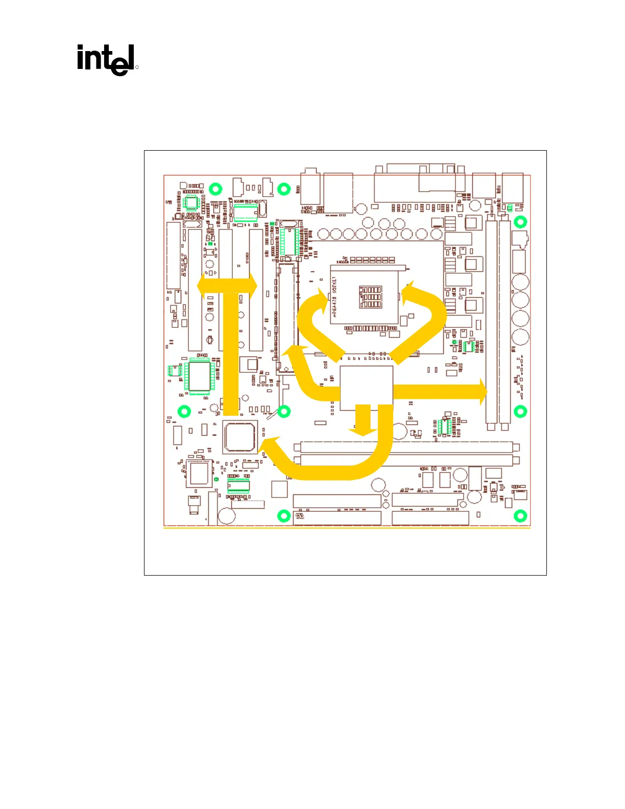
Figure 7 shows the general routing strategy for the 4-layer CRB.
Figure 7. Four-Layer Routing Strategy
RIMM Connector, Channel A
RIMM Connector, Channel A
RI
M
M
Co
nn
ect
or,
Ch
an
nel
B
RI
M
M
Co
nn
ect
or,
Ch
an
nel
B
MCH
Socket-478
G
P
Co
nn
ect
or
PC
I
Co
nn
ect
or
PC
I
Co
nn
ect
or
PC
I
Co
nn
ect
or
CN
R
Co
nn
ect
or
ICH
IDE Connector
IDE Connector
Floppy Connector
Hub Interface
R
A
C
RAC B
AGP
System Bus
System Bus
PCI Bus