Platform Clock Routing Guidelines
R
Intel
®
Pentium
®
4 Processor / Intel
®
850 Chipset Family Platform Design Guide 51
For 300/400 MHz RDRAM technology:
In clock routing sections ‘A’ and ‘D’, it is recommended that the clock signals (CTM/CTM# and
CFM/CFM#) be routed differentially.
For 533MHz RDRAM technology:
See Section 6.1.2.3 for CTM/CTM#, CFM/CFM# differential clock compensation requirements.
If the clock signals CTM/CTM# and CFM/CFM# are not routed differentially, then an additional
10pS per inch should be added to CTM/CTM# - MCH to first RIMM connector guideline only.
The clock signals shown in the example topology are 14 mils wide and routed differentially. There
must be a 22 mil ground isolation trace routed around the clock differential pair signals. The
22 mil ground isolation traces must be connected to ground with a via per every 1 inch. A 6-mil
gap is required between the clock signals and the ground isolation traces.
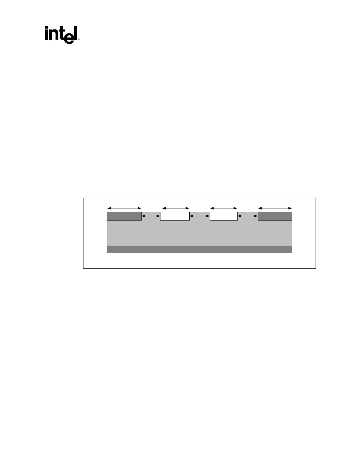
Figure 21. Differential Clock Routing
GROUND CLOCK CLOCK# GROUND
Ground/Power Pane
22 mils 22 mils14 mils 14 mils
6 mils 6 mils6 mils
Diff-Clk_route
NOTE: “CLOCK” stands for the signals CTM and CFM and “CLOCK#” stands for the signals CTM# and
CFM#.
In clock routing section ‘B’, the clock signals (CTM/CTM# and CFM/CFM#) are recommended to
be routed non-differentially due to the short routing lengths between RIMM connectors. An
example recommended topology for microstip non-differential clock routing is shown in
Figure 22.
Note: Clock trace widths and spacing may change for different prepreg thicknesses.
The clock signals shown in the example topology are routed with 18 mil wide traces. When
routing the clocks non- differentially, there must be a 10 mil ground isolation trace routed around
the single ended clock signals. The 10 mil ground isolation traces must be connected to ground
with a via per every 1 inch. A 6 mil gap is required between the clock signals and the ground
isolation traces.