Schematic Review Checklist
R
266 Intel
®
Pentium
®
4 Processor / Intel
®
850 Chipset Family Platform Design Guide
15.7.15 Power
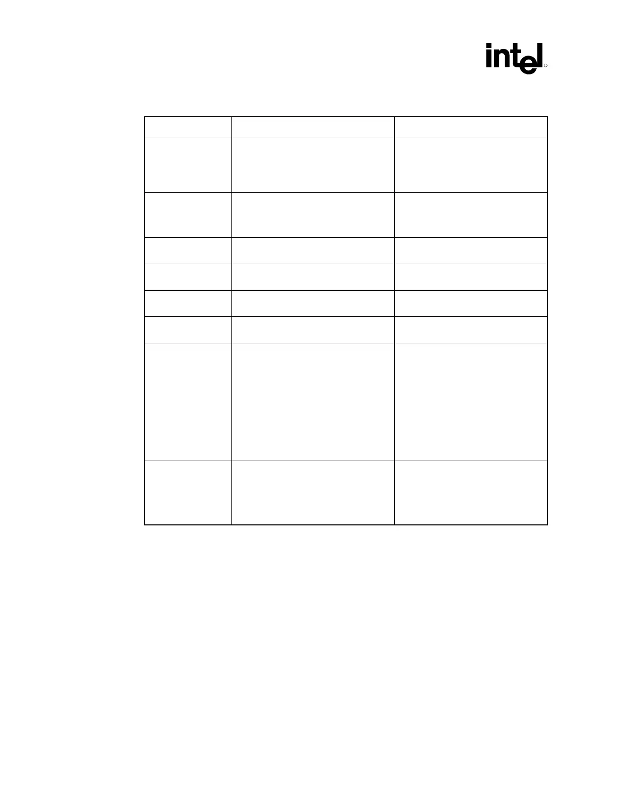
Checklist Items Recommendations Reason/Impact
V_CPU_IO[1:0] • The power pins should be connected
to the proper power plane for the
processor's asynchronous AGTL+
signals. Use one 0.1 µF decoupling
capacitor.
• Used to pull up all processor
interface signals.
VccRTC • No clear CMOS jumper on VccRTC.
Use a jumper on RTCRST# or a GPI,
or use a safemode strapping for Clear
CMOS
Vcc3_3 • Requires six 0.1 µF decoupling
capacitors.
VccSus3_3 • Requires one 0.1 µF decoupling
capacitor.
Vcc1_8 • Requires two 0.1 µF decoupling
capacitors.
VccSus1_8 • Requires one 0.1 µF decoupling
capacitor.
V5REF_SUS • Requires one 0.1 µF decoupling
capacitor.
• V5REF_SUS only affects 5 V
tolerance for USB OC[3:0]# pins and
can be connected to VccSUS3.3 or
5V_Always/5V_AUX if 5 V tolerance
on OC[3:0]# is not required. If 5 V
tolerance on OC[3:0]# is needed then
V5REF_SUS USB must be connected
to 5V_Always/5V_AUX which remains
powered during S5.
V5REF • V5REF is the reference voltage for 5 V
tolerant inputs in the ICH2. Tie to pins
VREF[2:1]. V5REF must power up
before or simultaneous to VCC3_3. It
must power down after or
simultaneous to VCC3_3.
• Refer to Section 12.6 for an
example circuit schematic that may
be used to ensure the proper
V5REF sequencing.