Component Quadrant Layout
R
Intel
®
Pentium
®
4 Processor / Intel
®
850 Chipset Family Platform Design Guide 29
2 Component Quadrant Layout
The quadrant layouts shown are approximations. The quadrant layout figures do not show the
exact component ball count; only general quadrant information is presented and is intended for
reference while using this document. Only the exact pin or ball assignment should be used to
conduct routing analysis. Refer to the following documents for pin or ball assignment information.
• Processor datasheet
• Intel
®
850 Chipset: 82850 Memory Controller Hub (MCH) Datasheet
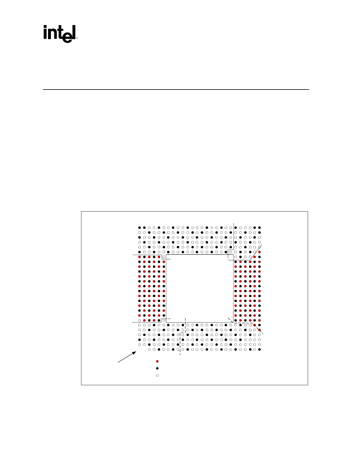
2.1 Processor Component Quadrant Layout
Figure 2 illustrates the quadrant layout of the processor. In the event that this information conflicts
with the processor datasheet, the datasheet data should be considered correct. All figures in this
section are from the topside perspective.
Figure 2. Processor Socket Quadrant Layout
Processor
=Power
=GND
=Signal
Clocks
ddress
Common Clock
Vcc/Vss
Data
Pin 1 in this corner
Quad_Lay_Processor