System Bus Routing
R
82 Intel
®
Pentium
®
4 Processor / Intel
®
850 Chipset Family Platform Design Guide
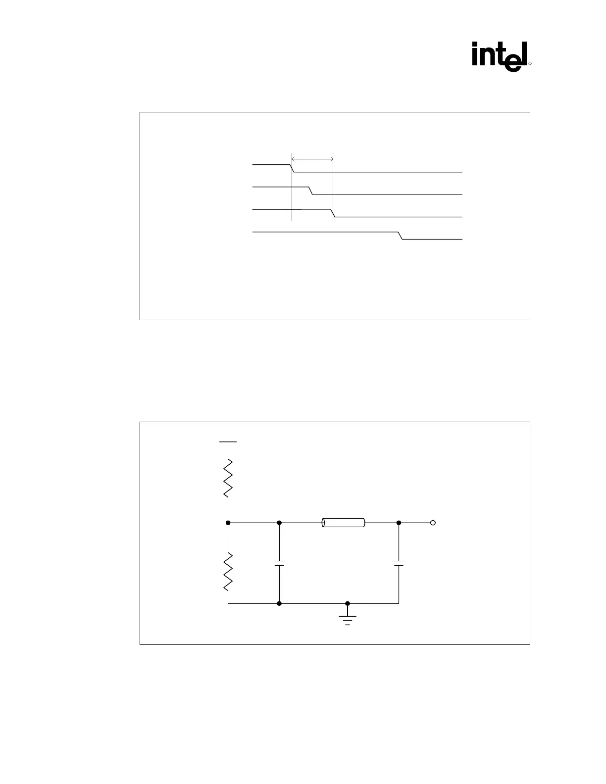
Figure 48. THERMTRIP# Power Down Sequence
THERMTRIP# Power Down Sequence
T1 < 0.5 seconds
Note: VID_GOOD is not a processor signal. This signal
is routed to the output enable pin of the voltage regluator
control silicon.
THERMTRIP#
VID_GOOD
VCC_CPU
PWRGOOD
T1
THERMTRIP_PWR-Down_Sequence
5.5 Intel
®
MCH System Bus Interface
A voltage divider network should supply host interface reference voltages locally as shown in
Figure 49, Figure 50 and as specified by Table 20.
Figure 49. Voltage Divider Network for Reference Voltage Generation
R2
V-Div_Ref_Gen
TLine
R1
1 uF
220 pF
L1 = 1.5" max
Socket Pin
Vcc
NOTES:
1. The MCH has only one dedicated voltage divider.
2. Decouple the voltage divider with a 1 µF capacitor.
3. Keep the voltage divider within 1.5 inches of the MCH Vref ball