Layout Review Checklist
R
276 Intel
®
Pentium
®
4 Processor / Intel
®
850 Chipset Family Platform Design Guide
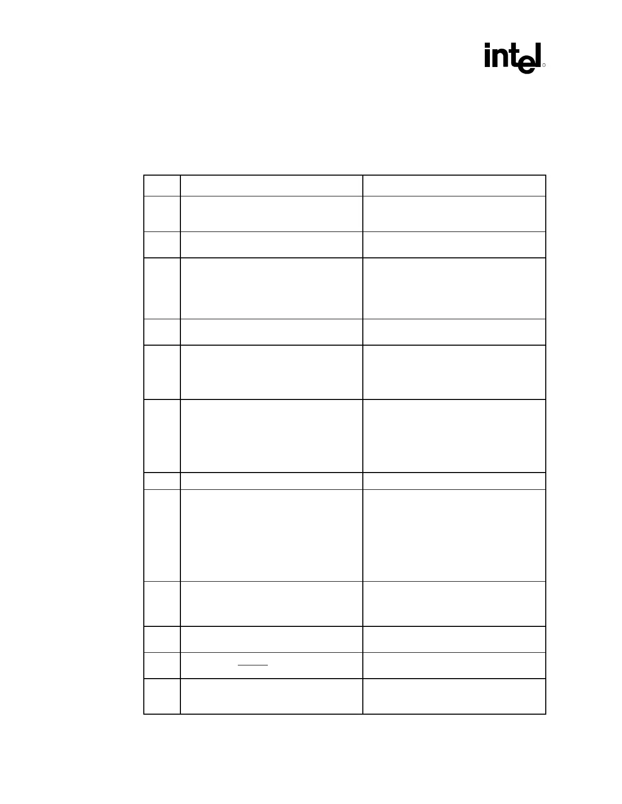
16.3 RAMBUS Technology Routing Guidelines
16.3.1 RSL Signals
√ Recommendations Reason/Impact
• MCH to 1
st
RIMM* connector of Channel A
or 1
st
RIMM connector of Channel B 1 inch–
6 inches
• Refer to Section 6.1.1.
• RIMM connector to RIMM connector of the
same channel 0.4 to 1 inch.
• Refer to Section 6.1.1.
• RIMM connector to Termination less than
2 inches.
• The trace length between the last RIMM
connector and the termination resistors
should be less than 2 inches.
• Length matching in this section is not
required.
• Refer to Section 6.1.3.
• RSL traces 18 mils trace width, 6-mil space,
and 10-mil ground flood, 6-mil space.
• Refer to Section 6.1.1.
• All signals must be length matched within
±10 mils of the Nominal RSL length as
described in this design guide. Ensure that
signals with a dummy via are compensated
correctly.
• Refer to Section 6.1.1.
• ALL RSL signals must have 1 via near the
MCH BGA pad. Signals routed on the
secondary side of the MB will have a “real
via” while signals routed on the top layer will
have a “dummy via”. Additionally, all signals
with a dummy via must have an additional
trace length of 25 mils.
• Refer to Section 6.1.2.2 for further
explanation and examples.
• Signals must “alternate” layers. • Refer to Section 6.1.2.4 of this document.
• At least 10 mils ground flood isolation
required around ALL RSL signals (ground
isolation must be exactly 6 mils from RSL
signals). Ground flood recommended for
isolation. This ground flood should be as
close to the MCH (and the 1st RIMM
connector) as possible. If possible, connect
the flood to the ground balls/pins on the
MCH/connector.
• To control cross talk and odd/even mode
velocity deltas.
• Refer to Section 6.1.1
• When RSL traces neckdown to exit the
MCH BGA, the minimum width is 15 mils
and the neckdown is no longer than 25 mils
in length.
• To minimize impedance discontinuities
• Uniform ground isolation flood is exactly
6 mils from the RSL signals at all times.
• Refer to Section 6.1.1.
• RSL traces Do NOT neckdown when routing
into the RIMM connector.
• To minimize impedance discontinuities
• If tight serpentining is necessary,
10-mil ground isolation MUST be between
serpentine segments
• A RSL signal CAN NOT serpentine so tightly
that the signal is adjacent to itself with no
ground isolation between the serpentines.