Intel® Pentium® 4 Processor in the 478-Pin Package Processor Power Distribution Guidelines
R
200 Intel
®
Pentium
®
4 Processor / Intel
®
850 Chipset Family Platform Design Guide
11.1.3 FMB1 Decoupling Requirements
For the processor voltage regulator circuitry to meet the transient specifications of the processor,
proper bulk and high frequency decoupling is required. The decoupling requirements for the
processor power delivery in this case are shown in Table 46.
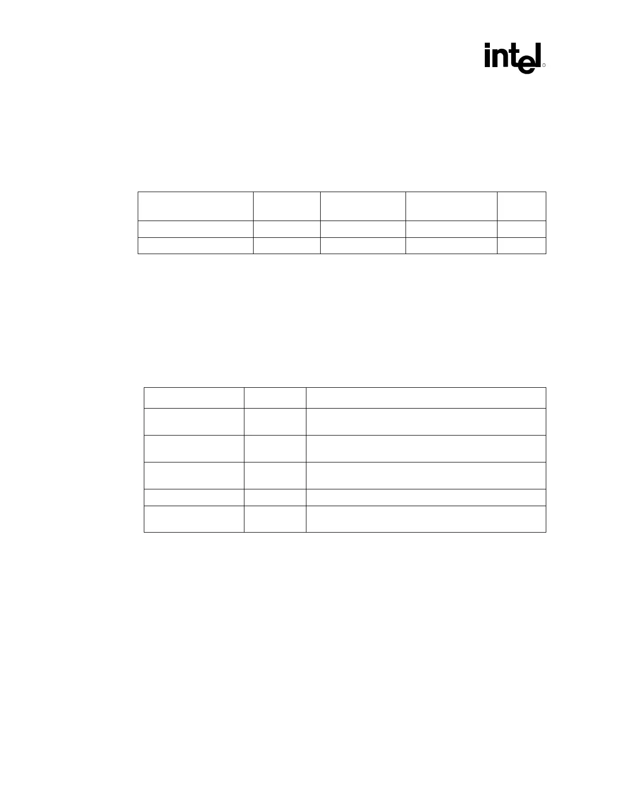
Table 46. Decoupling Requirements
Capacitance ESR (each) ESL (each) Ripple Current
Rating (each)
Notes
10 OS-CONs*, 560 µF 9.28 mΩ, max 6.4 nH, max 4.080 A
rms
1
30 1206 package, 10 µF 3.5 mΩ, typ. 1.15 pH, typ 1
NOTES:
1. The ESR, ESL and ripple current values in this table are based on the values used in power delivery
simulation by Intel and they are not vendor specifications.
2. The decoupling should be placed as close as possible to the processor power pins. Table 46 and
Table 47 illustrate the recommended placement. The placement drawings shows sites for
11 OS-CONs* and 38 1206 package 10 µF capacitors. The sites are populated as shown in Table 47
and the remaining sites are unpopulated. The voltage regulator designer should ensure that an
adequate amount of decoupling is present such that the circuit meets the processor specifications.
Table 47. Decoupling Locations
Type Number Location
560 µF OS-CONs* 5 North side of the processor as close as possible to the
keepout area for the retention mechanism
560 µF OS-CONs* 5 South side of the processor as close as possible to the
keepout area for the retention mechanism
1206 package, 10 µF 10 North side of the processor as close as possible to the
processor socket
1206 package, 10 µF 10 Inside the processor socket cavity
1206 package, 10 µF 10 South side of the processor as close as possible to the
processor socket