Introduction
R
20 Intel
®
Pentium
®
4 Processor / Intel
®
850 Chipset Family Platform Design Guide
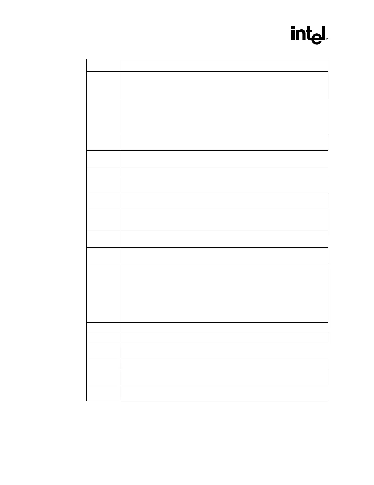
Term Definition
GTL+ GTL+ is the bus technology used by the Intel Pentium Pro processor. This is an incident
wave switching, open-drain bus with pull-up resistors that provide both the high logic level
and termination. It is an enhancement to the GTL (Gunning Transceiver Logic) bus
technology.
ISI Inter-symbol interference is the effect of a previous signal (or transition) on the interconnect
delay. For example, when a signal is transmitted down a line and the reflections due to the
transition have not completely dissipated, the following data transition launched onto the bus
is affected. ISI is dependent upon frequency, time delay of the line, and the reflection
coefficient at the driver and receiver. ISI can impact both timing and signal integrity.
Network The network is the trace of a Printed Circuit Board (PCB) that completes an electrical
connection between two or more components.
Network
Length
The distance between one agent pin and the corresponding agent pin at the far end of the
bus.
Overshoot Maximum voltage observed for a signal at the device pad.
Pad The electrical contact point of a semiconductor die to the package substrate. A pad is only
observable in simulation.
Pin The contact point of a component package to the traces on the system board. Signal quality
and timings can be measured at the pin.
Ringback The voltage that a signal rings back to after achieving its maximum absolute value.
Ringback may be due to reflections, driver oscillations, or other transmission line
phenomena.
System Bus The System Bus is the microprocessor bus of the Intel Pentium 4 processor. The System
Bus is not compatible with the P6 bus protocol.
Setup
Window
The time between the beginning of Setup to Clock (T
SU_MIN
) and the arrival of a valid clock
edge. This window may be different for each type of bus agent in the system.
SSO Simultaneous Switching Output (SSO) effects refers to the difference in electrical timing
parameters and degradation in signal quality caused by multiple signal outputs
simultaneously switching voltage levels (e.g., high-to-low) in the opposite direction from a
single signal (e.g., low-to-high) or in the same direction (e.g., high-to-low). These are
respectively called odd-mode switching and even-mode switching. This simultaneous
switching of multiple outputs creates higher current swings that may cause additional
propagation delay (or “push-out”), or a decrease in propagation delay (or “pull-in”). These
SSO effects may impact the setup and/or hold times and are not always taken into account
by simulations. System timing budgets should include margin for SSO effects.
Stub The branch from the bus trunk terminating at the pad of an agent.
Test Load Intel uses a 50 Ω test load for specifying its components.
Trunk The main connection, excluding interconnect branches, from one end agent pad to the other
end agent pad.
Undershoot Minimum voltage observed for a signal to extend below VSS at the device pad.
Victim A network that receives a coupled crosstalk signal from another network is called the victim
network.
V
REF
Guardband
A guardband defined above and below V
REF
to provide a more realistic model accounting for
noise such as V
TT
and V
REF
variation.