16. Close the input power tray cover, and secure it with the screw..
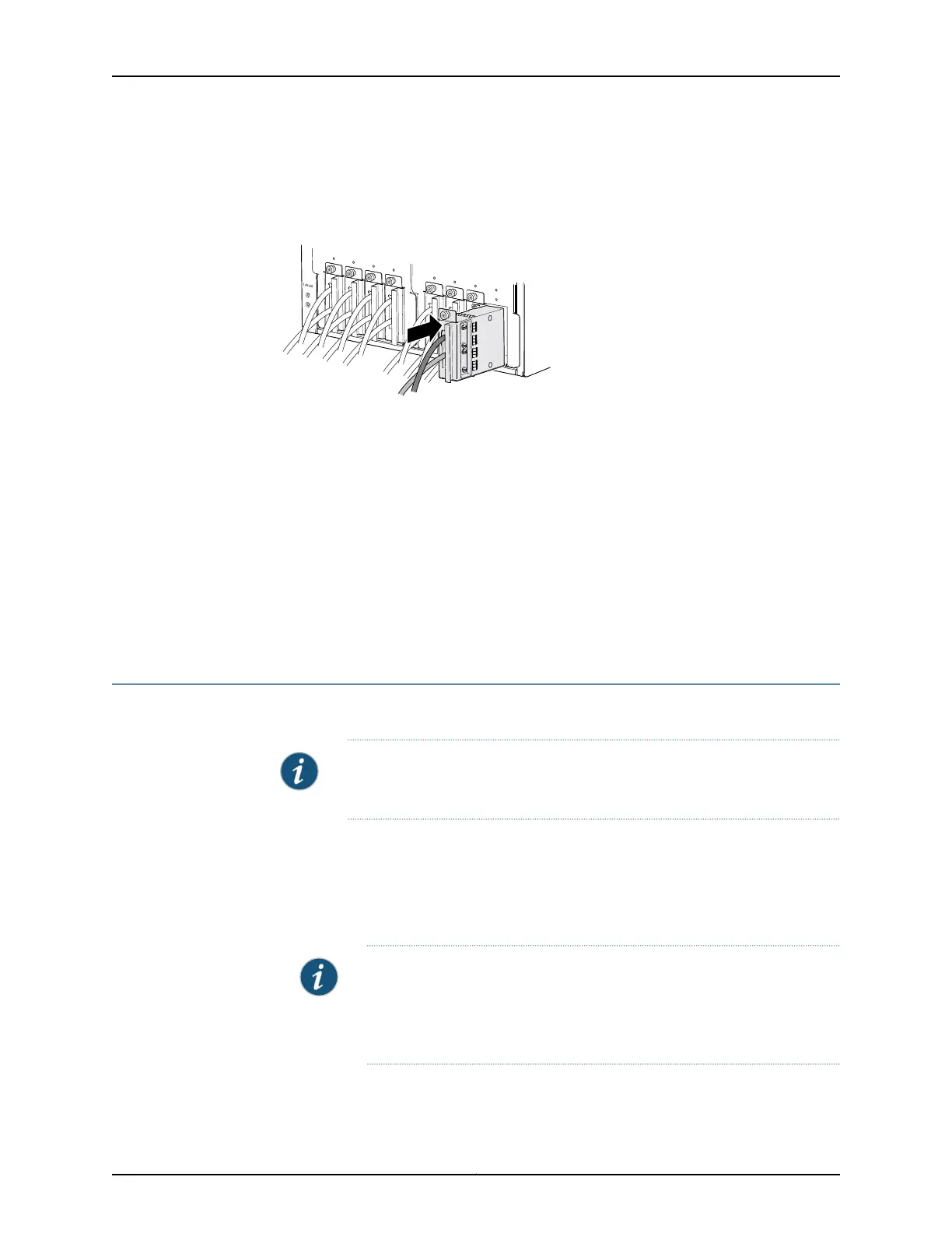
17. Insert the input power tray into the PDU.
Figure 45: Installing an Input Power Tray
18. Repeat the procedure for all input power trays in the PDU.
19. Repeat the procedure for the other PDU.
20. Verify that the DC power cables are not touching or blocking access to the components,
and that they do not drape where people could trip on them.
Related
Documentation
PTX5000 Power System Description on page 37•
• Tools and Parts Required to Provide Power to the PTX5000 Packet Transport Switch
on page 93
• Powering On the DC Powered PTX5000 Packet Transport Switch on page 96
Powering On the DC Powered PTX5000 Packet Transport Switch
To power on the DC-powered PTX5000 Packet Transport Switch:
NOTE: After powering off a power supply, you must wait at least 60 seconds
before powering it on again.
1. Verify that the power distribution units (PDUs) and power supply modules (PSMs)
are fully inserted in the chassis and that the captive screws on the faceplates are
tightened.
2. Verify that an external management device is connected to one of the Routing Engine
ports on the control board (AUXILIARY or CONSOLE).
NOTE: The management Ethernet port labeled HOST/ETHERNET on the
control board is not available until after the initial software configuration.
You can monitor the startup process during the initial installation using
devices connected to the AUXILIARY or CONSOLE ports.
3. Turn on the power to the external management device.
Copyright © 2012, Juniper Networks, Inc.96
PTX5000 Packet Transport Switch Hardware Guide

 Loading...


