components) fails, the backup can take over as the master. See “PTX5000 Host
Subsystem Description” on page 35.
If the Routing Engines are configured for nonstop active routing, the backup Routing
Engine automatically synchronizes its configuration and state with the master Routing
Engine. Any update to the master Routing Engine state is replicated on the backup
Routing Engine. If the backup Routing Engine assumes mastership, packet forwarding
continues through the packet transport switch without interruption. For more
information about nonstop active routing, see the Junos OS High Availability Configuration
Guide.
•
Centralized Clock Generators (CCGs)—The packet transport switch has a standard
configuration of one CCG. If two CCGs are installed, the second CCG functions as
backup. If one CCG fails, the other becomes the master CCG. Mastership of the CCG
is independent of the host subsystem, so routing functions are not affected. See
“PTX5000 Centralized Clock Generator Description” on page 16.
•
Power system—The packet transport switch has up to two power distribution units
(PDUs), which share the load evenly. If one PDU fails in a fully redundant power system
that includes two PDUs and eight power supply modules (PSMs), the other PDU can
provide full power to the packet transport switch indefinitely. PSM redundancy varies
depending on the number of PSMs and number of FPCs. See the “PTX5000 Power
System Description” on page 37 for more information about power system redundancy.
•
Cooling system—The cooling system has redundant components, which are controlled
by the host subsystem. If one of the fans fails, the host subsystem increases the speed
of the remaining fans to provide sufficient cooling for the packet transport switch
indefinitely. See “PTX5000 Cooling System Description” on page 18.
Related
Documentation
PTX5000 Packet Transport Switch Description on page 3•
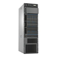
PTX5000 Chassis Description
The PTX5000 Packet Transport Switch chassis is a rigid sheet metal structure that
houses all the other hardware components (see Figure 3 on page 13 and Figure 4 on
page 14). The chassis measures 62.5 in. (158.8 cm) high, 33.2 in. (84.3 cm) deep, and
17.43 in. (44.3 cm) wide. The chassis can be installed into many types of racks or cabinets.
The chassis includes the following features (see Figure 3 on page 13 and Figure 4 on
page 14):
•
Front-mounting flanges for mounting in a four-post rack or cabinet.
•
Center-mounting metal brackets for center-mounting in an open-frame rack.
•
Handles on each side to facilitate positioning the packet transport switch in the rack.
Do not use the handles to lift the packet transport switch.
•
Two electrostatic discharge (ESD) points (banana plug receptacles), one front and
one rear.
Copyright © 2012, Juniper Networks, Inc.12
PTX5000 Packet Transport Switch Hardware Guide

 Loading...