CAUTION: Before removing or installing components, attach an ESD strap
to an ESD point, and place the other end of the strap around your bare
wrist. Failure to use an ESD strap could result in damage to the hardware
components.
WARNING: Thepackettransport switchmust be connected to earth ground
during normal operation.
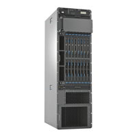
Figure 3: Front View of PTX5000 Chassis
6—1— FPCs and PICsFront-mounting flange
7—2— ESD pointCraft interface
8—3— Lower horizontal fan trayUpper horizontal fan tray
9—4— Horizontal air filterCable management system
10—5— Power supply module door and power
supply modules air filter
Vertical fan tray and vertical air filter
13Copyright © 2012, Juniper Networks, Inc.
Chapter 3: PTX5000 Hardware Components Overview

 Loading...