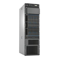
Figure 4: Rear View of PTX5000 Chassis
6—1—
Control board CB1 and Routing Engine RE1
Center-mounting bracket
7—2— ESD pointsAir exhaust
8—3— Power distribution units (PDUs)Centralized clock generators (CCGs)
9—4— Chassis grounding pointsSwitch interface boards (SIBs)
5—
Control board CB0 and Routing Engine RE0
Related
Documentation
PTX5000 Packet Transport Switch Description on page 3•
• PTX5000 Physical Specifications on page 255
• Rack Requirements for the PTX5000 Packet Transport Switch on page 56
• PTX5000 Chassis Grounding Cable and Lug Specifications on page 259
PTX5000 Midplane Description
The midplane is located in the center of the chassis and forms the rear of the Flexible
PIC Concentrator (FPC) card cage. The FPCs install into the midplane from the front of
the chassis; and the Switch Interface Boards (SIBs), Routing Engines, control boards,
Centralized Clock Generators (CCGs), and power distribution units (PDUs) install into
Copyright © 2012, Juniper Networks, Inc.14
PTX5000 Packet Transport Switch Hardware Guide

 Loading...