PSM Components
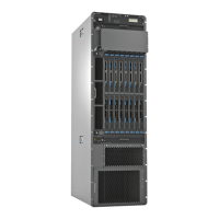
Figure 22 on page 40 shows the PSM. Each PSM weighs approximately 10.6 lb (4.8 kg).
Figure 22: PSM
g006131
DC IN OK
DC OUT OK
FAULT
PTX5000 Power Zones and PSM Fault Tolerance
The power system contains three power zones. Table 18 on page 40 describes which
components are powered by each zone and PSM.
Table 18: Components Powered by Each Zone
ComponentPSMZone
Fan trays00
The craft interface and the following components installed in the rear
card cage: Routing Engines, control boards, CCGs, and SIBs.
•
Channel 1: Routing Engines and control boards
•
Channel 2: SIBs, CCGs, and craft interface
11
Any four FPCs in slots FPC0 through FPC722
Any four FPCs in slots FPC0 through FPC73
Copyright © 2012, Juniper Networks, Inc.40
PTX5000 Packet Transport Switch Hardware Guide

 Loading...