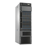
Figure 2: Rear View of the PTX5000 Packet Transport Switch
6—1—
Control board CB1 and Routing Engine RE1
Center-mounting bracket
7—2— ESD pointAir exhaust
8—3— Power distribution units (PDUs)Centralized clock generators (CCGs)
9—4— Chassis grounding pointsSwitch interface boards (SIBs)
5—
Control board CB0 and Routing Engine RE0
Related
Documentation
• PTX5000 System Architecture Description on page 7
• PTX5000 Chassis Description on page 12
• Overview of Installing the PTX5000 Packet Transport Switch on page 53
5Copyright © 2012, Juniper Networks, Inc.
Chapter 1: PTX5000 Packet Transport Switch Overview

 Loading...