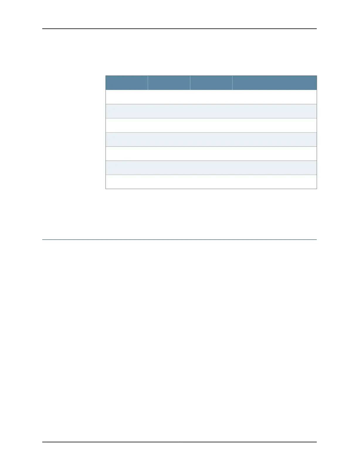
Table 53: RJ-45 Connector Pinouts for the PTX5000 AUXILIARY and
CONSOLE Ports (continued)
DescriptionDirectionSignalPin
Transmit Data–>TxD3
Data Terminal Ready–>DTR4
Signal Ground—Ground5
Data Set Ready<–DSR6
Request To Send–>RTS7
Clear To Send<–CTS8
Ring Indicator<–RING9
Related
Documentation
PTX5000 Control Board Description on page 22•
• Connecting the PTX5000 Packet Transport Switch to a Management Console or
Auxiliary Device on page 86
PTX5000 Alarm Relay Contact Wire Specifications
For management and service operations, you can connect the packet transport switch
to external alarm-reporting devices through the alarm relay contacts on the craft interface.
You must provide a wire with gauge between 28-AWG and 14-AWG (0.08 and 2.08
mm
2
).
Related
Documentation
• PTX5000 Craft Interface Description on page 26
• Connecting the PTX5000 Packet Transport Switch to an External Alarm-Reporting
Device on page 87
273Copyright © 2012, Juniper Networks, Inc.
Appendix E: Packet Transport Switch Cable, Wire, and Pinout Specifications and Guidelines

 Loading...


