PTX5000 FPC Overview
•
PTX5000 FPC Description on page 32
•
PTX5000 FPC LEDs on page 34
•
PTX5000 FPCs Supported on page 35
PTX5000 FPC Description
•
FPC Slots on page 32
•
FPC Function on page 32
•
FPC Components on page 32
•
FPC Terminology on page 33
•
Identifying the FPCs on page 33
FPC Slots
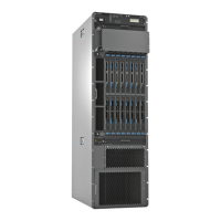
Up to eight FPCs install vertically in the front of the packet transport switch. The FPC
slots are numbered FPC0 through FPC7, left to right. If a slot is not occupied by an FPC,
an FPC blank panel must be installed to shield the empty slot and to allow cooling air to
circulate properly through the packet transport switch.
FPC Function
FPCs house the PICs that connect the PTX5000 Packet Transport Switch to network
media. The main function of an FPC is to connect the PICs installed in it to the other
PTX5000 Packet Transport Switch components. The Packet Forwarding Engine receives
incoming packets from the PICs installed on the FPC and forwards them through the
switch planes to the appropriate destination port. In a maximum configuration with eight
FPCs installed, the Packet Forwarding Engines can forward up to 4800 million packets
per second (Mpps) for all packet sizes. The PTX5000 Packet Transport Switch provides
up to 8 terabits per second (Tbps), full duplex switching (4 Tbps of any-to-any,
nonblocking, half-duplex switching).
When you install an FPC into a functioning packet transport switch, the Routing Engine
downloads the FPC software, the FPC runs its diagnostics, and the PICs housed on the
FPC are enabled. Forwarding on other FPCs continues uninterrupted during this process.
FPC Components
Each FPC consists of the following components:
•
FPC card carrier
•
Four Packet Forwarding Engines, consisting of Lookup ASICs and the Queuing and
Memory Interface ASICs
•
Processor Mezzanine Board (PMB), which includes a 1.2-GHz CPU, 4 GB of SDRAM,
and two Fast Ethernet interfaces.
Copyright © 2012, Juniper Networks, Inc.32
PTX5000 Packet Transport Switch Hardware Guide

 Loading...