Base System +1 host subsystem + 1 CCG + 6 PSM + cooling system ( full speed - normal
speed) + 8 FPCs + 16 PICs=
28.2 A + 3.7 A + 0.3 A + 6(1.0) A + (63.8 A- 11.6 A) + 8(11.6) + 16(1.6) A
28.2 A + 3.7 A + 0.3 A + 6.0 A + 52.2 A + 92.8 A + 25.6 A = 208.8 A @ –48 VDC =10,022
W
•
Example of calcualting typical system thermal output for a configuration:
Watts DC/0.293 = BTU/hr
10,022 W/0.293 = 34,205 BTU/hr
Related
Documentation
PTX5000 Power System Description on page 37•
• Connecting DC Power to the PTX5000 Packet Transport Switch on page 94
• PTX5000 DC Power System Electrical Specifications on page 260
• PTX5000 DC Power Cable and Lugs Specifications on page 263
• PTX5000 DC Power Distribution on page 264
PTX5000 DC Power Cable and Lugs Specifications
•
DC Power Cables on page 263
•
DC Power Lugs on page 264
DC Power Cables
You must supply the DC power cables which meet the specifications in Table 49 on
page 263, or as required by the local code, laws, and standards.
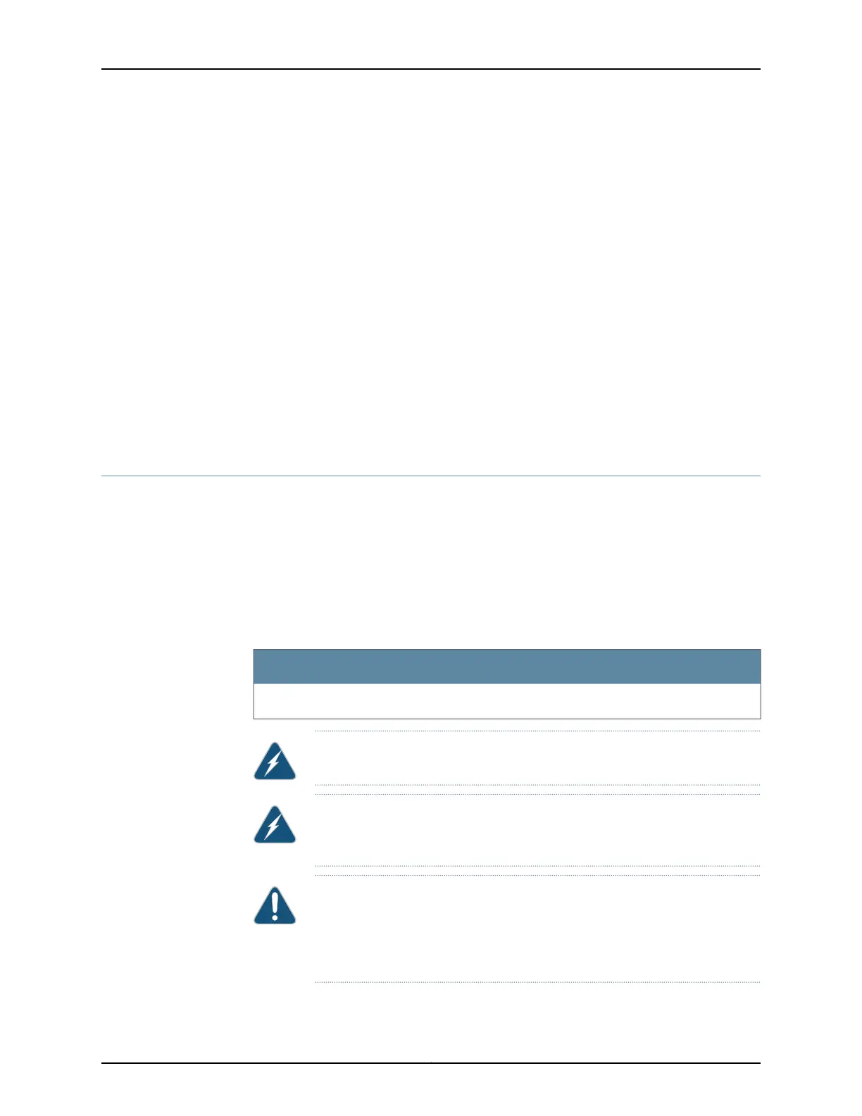
Table 49: Power Cable Specifications
Specification
0-AWG (53 mm
2
)
WARNING: For field-wiring connections, use copper conductors only.
WARNING: DC Power cables must not block access to packet transport
switch components or drape where people could trip on them.
CAUTION: Before packet transport switch installation begins, a licensed
electrician must attach a cable lug to the power cables that you supply. A
cable with an incorrectly attached lug can damage the packet transport
switch.
263Copyright © 2012, Juniper Networks, Inc.
Appendix D: Power Guidelines, Requirements, and Specifications

 Loading...


