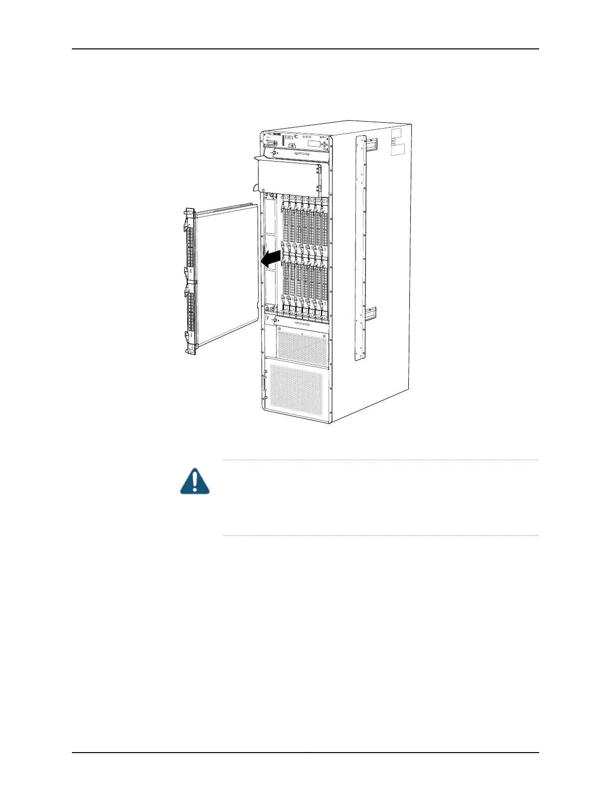
Figure 60: Removing an FPC
g006182
FPC-PTX
P1-A
P1-PTX
24-10GE-SFPP
STATUS
ONLINE
0
1
2
3
4
5
6
7
8
9
10
11
12
13
14
15
16
17
18
19
20
21
22
TX
TX
RX
RX
23
OFFLINE
P1-PTX
24-10GE-SFPP
STATUS
ONLINE
0
1
2
3
4
5
6
7
8
9
10
11
12
13
14
15
16
17
18
19
20
21
22
TX
TX
RX
RX
23
OFFLINE
Installing a PTX5000 FPC
CAUTION: TheFPC power connector is locatedin the corner where the bottom
and the connector edges meet. If a power connector prong becomes bent, it
no longer aligns with the female connector on the midplane, and the FPC no
longer functions.
To install an FPC (see Figure 61 on page 176 and Figure 62 on page 178):
1. Attach an electrostatic discharge (ESD) grounding strap to your bare wrist, and connect
the strap to one of the ESD points on the chassis.
2. Place the FPC on an antistatic mat.
3. Take each PIC to be installed in the replacement FPC out of its electrostatic bag and
identify the slot on the FPC where it will be connected.
4. Verify that each fiber-optic PIC has a rubber safety cap covering the PIC transceiver.
If it does not, cover the transceiver with a safety cap.
5. Install each PIC into the appropriate slot on the FPC. For information about installing
a PIC, see the installation instructions in “Replacing a PTX5000 PIC” on page 178.
175Copyright © 2012, Juniper Networks, Inc.
Chapter 15: Replacing Packet Transport Switch Hardware Components

 Loading...


