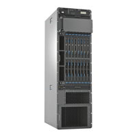
Table 3: PTX5000 Hardware Components (continued)
DescriptionCLI OutputHardware LabelModel NumberComponent
“PTX Series PIC Description” on
page 36
PTX5000 Packet Transport
Switch PIC Guide
24x 10GE (LAN)
SFP+
P1-PTX
24-10GE-SFPP
P1-PTX-24-10GE-SFPPPIC
2x 100GE CFPP1-PTX
24-100GE-CFP
P1-PTX-2-100GE-CFP
2x 40GE CFPP1-PTX-2-40GE-CFPP1-PTX-2-40GE-CFP
N/AN/APIC-BLANK-PTX
“PTX5000 Power System
Description” on page 37
DC Power Dist UnitN/APDU-PTX-DC-120Power
system
including the
power
distribution
units (PDUs)
and power
supply
modules
(PSMs)
DC 12V Power
Supply
N/APSM-PTX-DC-120
N/AN/APSM-BLANK-PTX
“PTX5000 Routing Engine
Description” on page 44
RE-DUO-2600N/ARE-DUO-C2600-16GRouting
Engine
N/AN/ARE-BLANK
“PTX5000 Switch Interface
Board Description” on page 48
SIB-I-8SSIB-I-PTX5008SIB-I-PTX5008Switch
interface
board (SIB)
Related
Documentation
PTX5000 Packet Transport Switch Description on page 3•
• PTX5000 Component Redundancy on page 11
PTX5000 Component Redundancy
The PTX5000 Packet Transport Switch is designed so that no single point of failure can
cause the entire system to fail. The following major hardware components are redundant:
•
Switch Interface Boards (SIBs)—The PTX5000 Packet Transport Switch has nine SIBs.
All nine SIBs are active and can sustain full throughput rate. The fabric plane can
tolerate one SIB failure without any loss of performance. See “PTX5000 Switch
Interface Board Description” on page 48.
•
Host subsystem—The host subsystem consists of a Routing Engine functioning together
with a control board. To operate, each host subsystem requires a Routing Engine
installed in a slot in the control board. The packet transport switch can have one or
two host subsystems. If two host subsystems are installed, one functions as the master
and the other functions as the backup. If the master host subsystem (or either of its
11Copyright © 2012, Juniper Networks, Inc.
Chapter 3: PTX5000 Hardware Components Overview

 Loading...