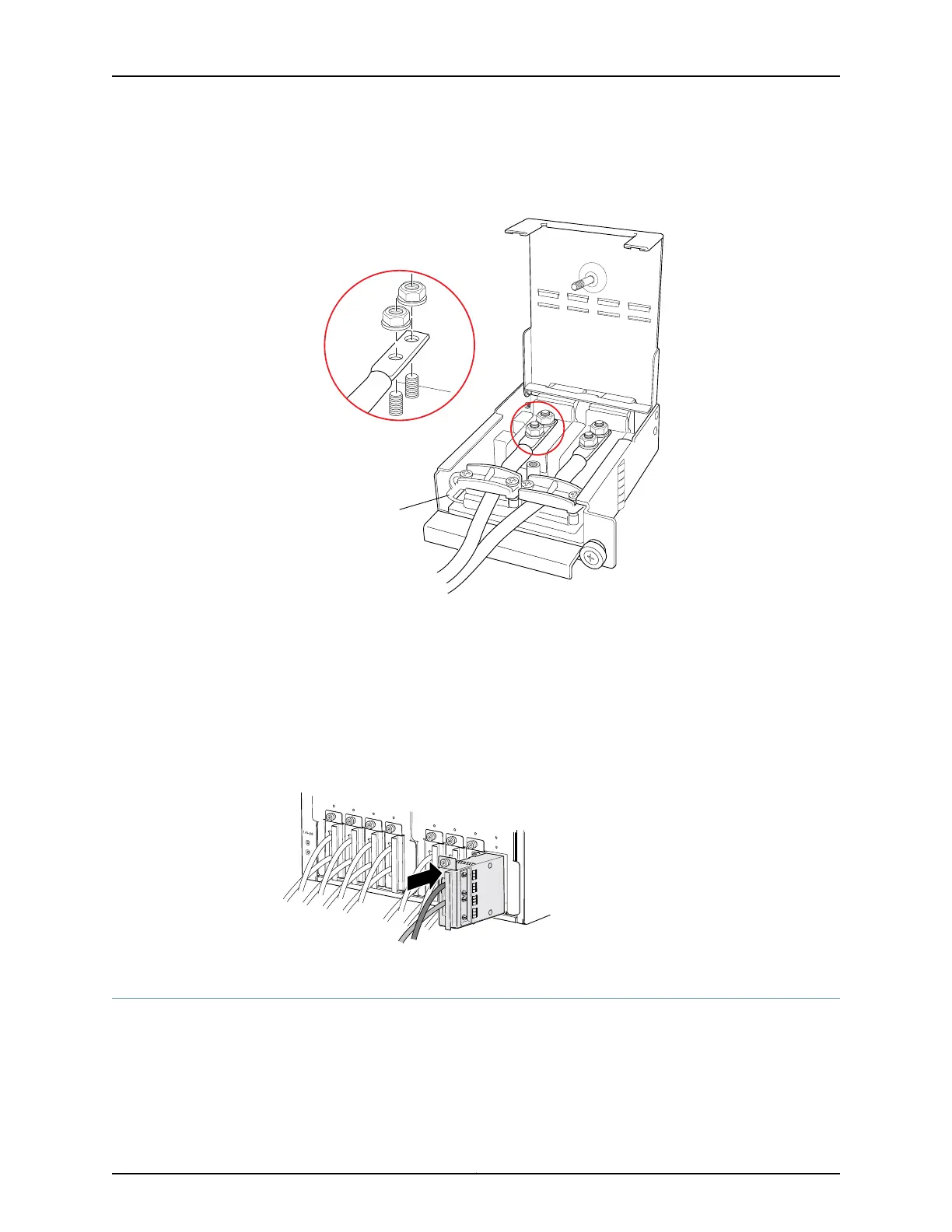
Figure 77: Connecting the DC Source Power Cable Lugs to an Input Power
Tray
7. Tighten the cable restraint over the DC power cables.
8. Verify that the source power cables are connected to the appropriate terminal: the
positive (+) source cable to the return terminal (labeled RTN) and the negative (–)
source cable to the input terminal (labeled –48V).
9. Close the input power tray cover, and secure it with the screw..
10. Insert the input power tray into the PDU.
Figure 78: Installing an Input Power Tray
Replacing a PTX5000 PSM
1.
Removing a PTX5000 PSM on page 202
2.
Installing a PTX5000 PSM on page 202
201Copyright © 2012, Juniper Networks, Inc.
Chapter 15: Replacing Packet Transport Switch Hardware Components

 Loading...


