• Replacing a PTX5000 Horizontal Fan Tray on page 189
• Replacing a PTX5000 Vertical Fan Tray on page 191
Troubleshooting the PTX5000 Control Boards
Problem The following alarms and LEDs indicate a problem with a control board:
• A red alarm indicates that the control board has failed or has been removed.
• A yellow alarm indicates that the Ethernet switch in the control board has failed.
• The yellow FAIL LED on the control board faceplate is lit.
• The green OK LED on the control board faceplate is not lit.
• The red host subsystem FAIL LED on the craft interface is lit.
• The green host subsystem OK LED on the craft interface is not lit.
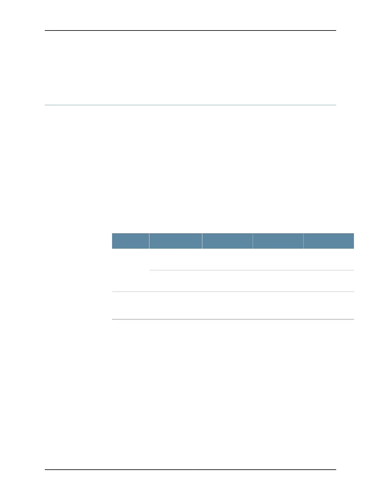
In Table 35 on page 135, the text in the column labeled ”LCD Message” appears in the
display of the craft interface. The text in the column labeled “CLI Message” appears in
the output from the show chassis alarms command.
Table 35: Chassis Alarm Messages for the Control Boards
SolutionAlarm ConditionCLI MessageLCD MessageAlarm Type
Replace the control
board
A control board
failed.
CB cb-number
Removed
CB cb-number
Removed
Red
Reinstall the
control board
A control board has
been removed.
CB cb-number
Failure
CB cb-number Failure
Replace the control
board.
The Ethernet switch
on the control
board has failed.
CB cb-number
Ethernet Switch
Failure
CB cb-number
Ethernet Switch
Failure
Yellow
Solution To troubleshoot the T1600 control boards:
1. Check the LEDs on the faceplate of each control board.
2. Check the LEDs on the craft interface.
3. Use the CLI to check for alarms. Issue the show chassis alarms command to view the
alarms.
Related
Documentation
PTX5000 Control Board Description on page 22•
• PTX5000 Control Board LEDs on page 24
• PTX5000 Host Subsystem Description on page 35
• PTX5000 Craft Interface Description on page 26
• PTX5000 Craft Interface LEDs on page 28
135Copyright © 2012, Juniper Networks, Inc.
Chapter 14: Troubleshooting Packet Transport Switch Hardware Components

 Loading...


