General Power Meter Functions 2
Keysight N1911A/1912A User’s Guide 127
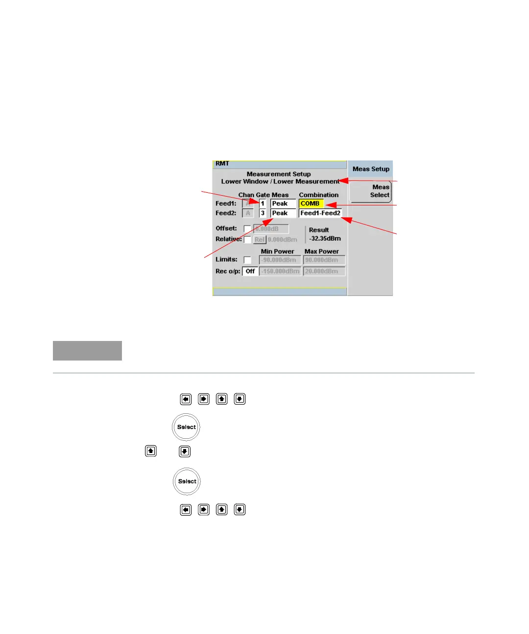
Combined Measurement
Figure 2-58 shows a Combined Measurement configuration; Channel A, gate 1
peak power minus gate 3 peak power, to be displayed in the lower measurement
line of the lower display window. (For single channel power meter (N1911A), the
Channel field will be disabled, as shown in Figure 2-58).
Figure 2-58 Measurement Setup showing combined configuration
1 Use the , , , , to highlight the Combination function field.
2 Press to display the Function pop-up (see Figure 2-55) and use the
and to highlight Combined.
3 Press to complete the entry.
4 Use the , , , , to highlight the measurement type field.
Gate fields
Measurement fields
Selected Window/
Measurement
Function field
Combination field
The Gate field is disabled if Trigger Acquisition is Free Run.