Using P-Series Power Sensor 3
Keysight N1911A/1912A User’s Guide 159
Trace Control
Press to display the Trace Control menu. Setting the trace features
are described in greater details in “Setting up the Channel Trace” on page 92.
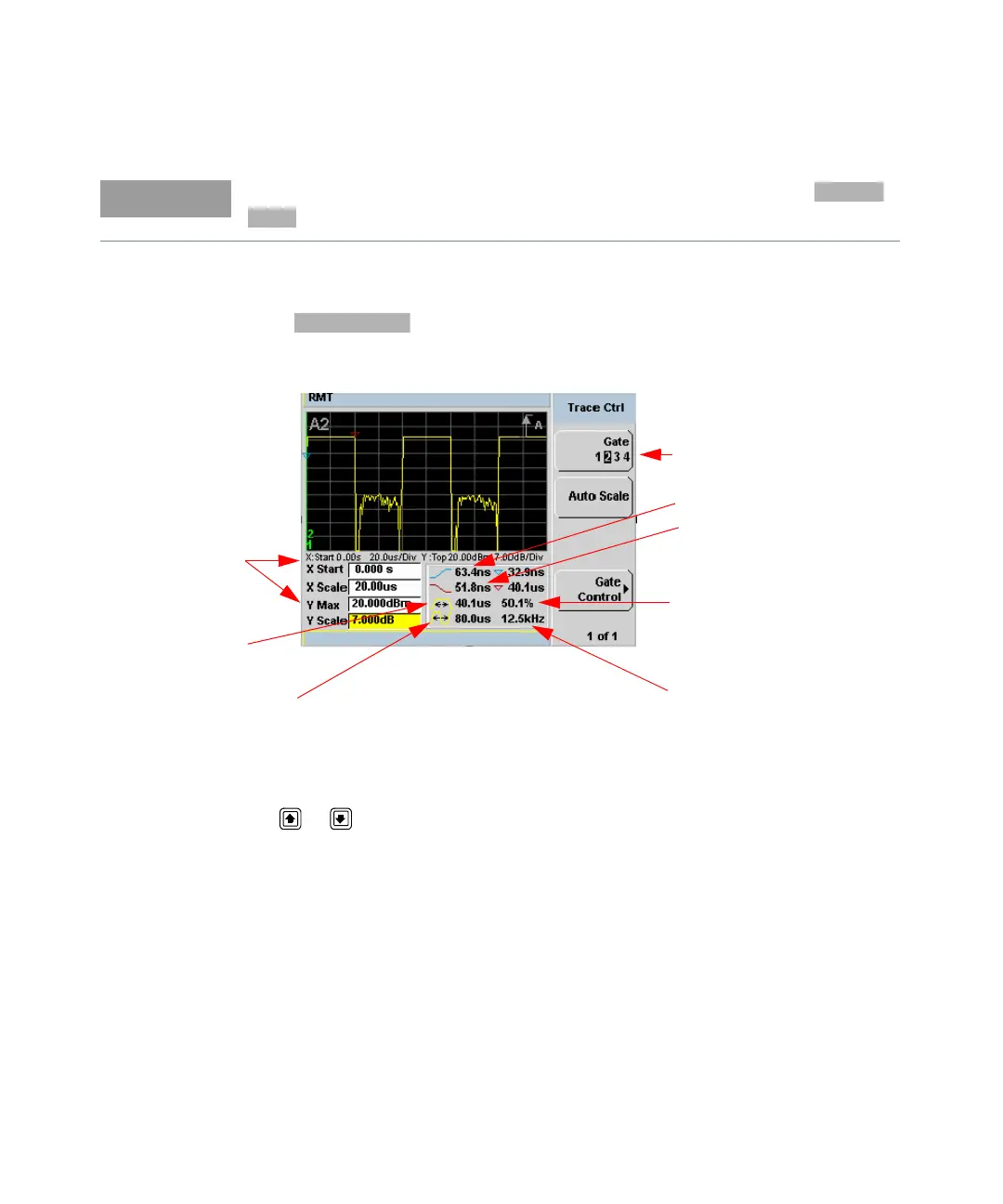
Figure 3-6 Trace display with trace control menu
The fields on the lower left of the screen are the X and Y trace setup fields. Using
the or keys you can highlight the item and change its value. (See
Figure 3-6)
The table on the lower right of the screen shows the eight automatic time
measurements performed on the first complete captured pulse after the trigger.
The eight measurements are rise time, fall time, time to positive occurrence, time
to negative occurrence, pulse width, pulse period (pulse repetitive interval), pulse
repetitive frequency and duty cycle.
The current settings of the X and Y scale are displayed on the reporting line above
both tables.
You can also setup the trigger delay in the Trigger menu, by pressing ,
and entering a value in the pop-up window.
Trace settings
Pulse width
Pulse period
Gate 2 active
Rising edge
Falling edge
Duty cycle
Pulse repetitive frequency