General Power Meter Functions 2
Keysight N1911A/1912A User’s Guide 87
Setting Measurement Channel Gates
A system of gates, controlled by and referenced to a trigger point, is used to
obtain measurement data from a captured trace. The trace data within each gate
period is subsequently used for the individual measurement calculations. Up to 4
gates can be set up for each channel. Figure 2-22 shows an example of 4 gates
setup to perform the following measurements simultaneously:
– Average power level of the pulse:
Gate 1, average measurement
– Average “off” power level ahead of the pulse:
Gate 2, average measurement
– Peak to average ratio:
Gate 1, peak-to-average measurement
–Pulse drop:
Gate 3, average measurement, minus Gate 4, average measurement
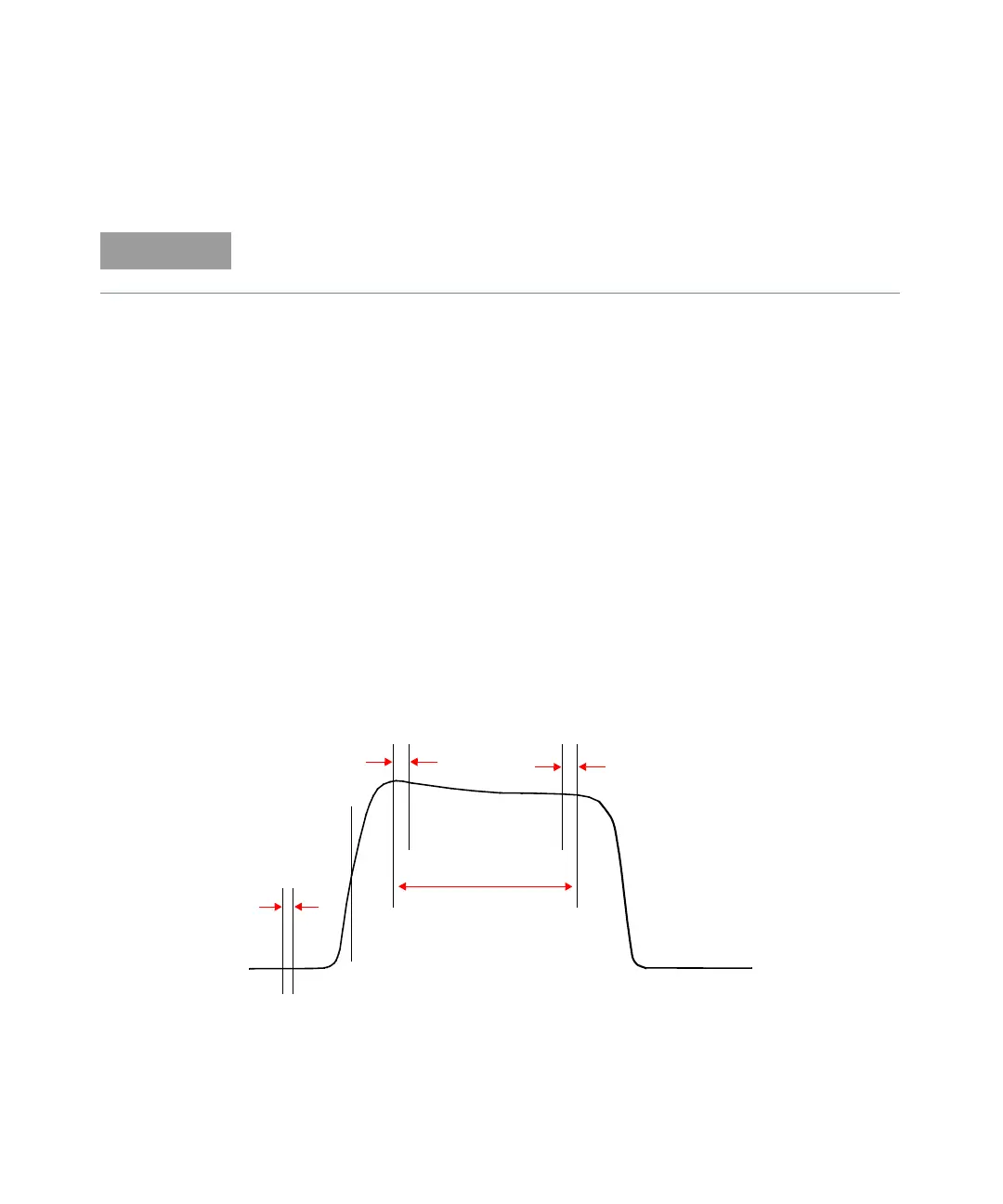
Figure 2-22 Example of measurement gates
This feature is only available when a P-Series or an E-Series E9320 power sensor
is connected.
Gate 1
Gate 4
Gate 3
Gate 2
Trigger