136 Keysight N9038A MXE Service Guide
Input Selection & Level Control
Input Selection & Level Control Section Troubleshooting
Input Selection & Level Control Section Troubleshooting
This section will describe how to verify the performance of the following
assemblies:
— A9 Attenuator A
— A10 Attenuator B
— A23 Limiter Assembly
—SW1 Cal Switch
—SW2 Transfer Switch
A9 Attenuator A
There are two different A9 Attenuator A assemblies used in the N9038A; one
for the Option 503, 508, and 526 instruments and one for the Option 544
instruments. While the overall amount of attenuation is the same for all
instruments, the distribution of the attenuator sections within the attenuators
is not quite the same. The Option 503, 508, and 526 A9 Attenuator A has a
total of only 4 dB of attenuation, while the Option 544 attenuator has 10 dB.
Also, the Option 544 attenuator does not have the AC/DC coupling selection
that the one for Option 503, 508, and 526 does.
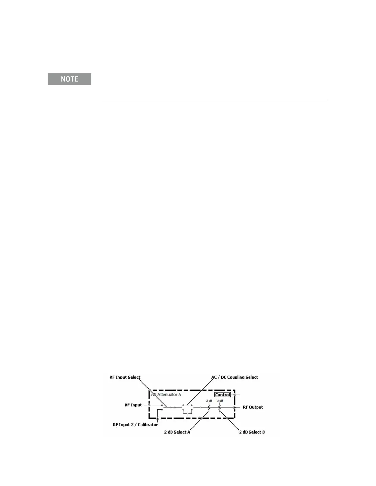
Option 503, 508, & 526
There are three different functions that the A9 Attenuator A assembly provides,
as shown in Figure 4-2. These functions will be verified with the procedure in
this section. They are:
1. AC / DC Coupling Selection
2. RF Input Selection
3. Attenuation Selection (0 to 4 dB in 2 dB steps)
Figure 4-2 A9 Attenuator A Functions - Option 503, 508, & 526
Refer to Chapter 15, “Block Diagrams.”.

 Loading...


