Keysight N9038A MXE Service Guide 311
Reference Assembly
A16 Reference Assembly Troubleshooting
Assembly Output Signal Frequency & Amplitude Verification
With the use of a spectrum analyzer, verify the frequency and amplitude of the
different A16 Reference assembly outputs as outlined in Table 9-3. In order to
measure these signals, you will need to remove the instrument dress cover
(MP24) and top brace (MP10). Refer to Chapter 18, “Assembly Replacement
Procedures” for instructions on removing these covers.
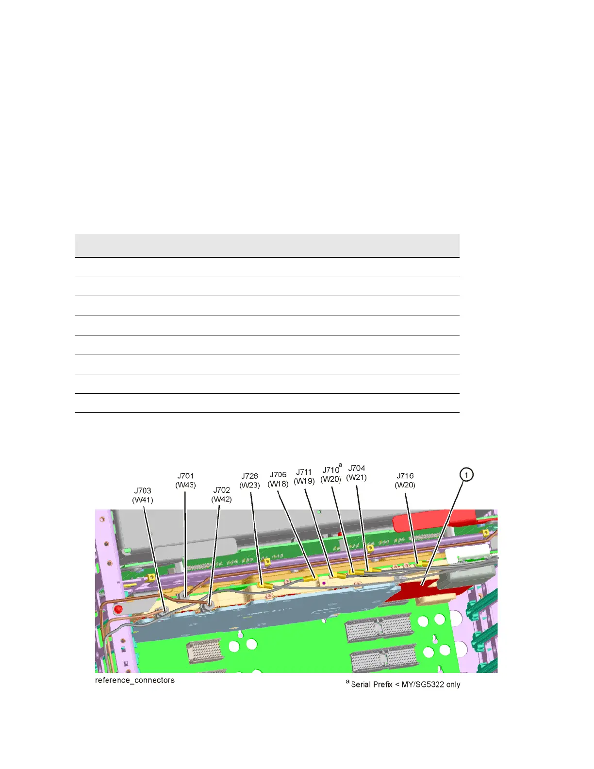
The location of the connection for each of the A16 Reference assembly signals
can be found in Figure 9-3 and the description, frequency, and amplitude of
each can be found in Table 9-3.
Figure 9-3 A16 Reference Board Assembly Cable Locations
Table 9-3 A16 Reference Assembly Outputs
Signal Signal Location Frequency (MHz) Power Level (dBm)
Digital IF Reference J710 10 MHz +3 dBm
50 MHz Calibrator J701 50 MHz −25 dBm
E-Cal Reference J705 50 MHz −27.5 dBm
Digital IF Reference J716 100 MHz +13 dBm
3rd LO J711 300 MHz +10 dBm
4.8 GHz Calibrator J701 4800 MHz −28 dBm
2nd LO (Low Band) J702 4800 MHz +11 dBm
1st LO Reference J703 4800 MHz +3 dBm
Wideband IF Reference J718 2400 MHz +7 dBm

 Loading...


