Keysight N9038A MXE Service Guide 595
Assembly Replacement Procedures
CPU Assembly
CPU Assembly
Removal
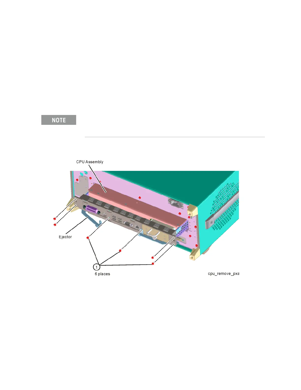
1. Refer to Figure 18-49. Remove the six screws (1) (0515-0372) attaching
the CPU assembly to the chassis.
2. The CPU assembly can be removed from the chassis by pulling straight out
the back. Use the two ejectors to pull the CPU assembly out from the
chassis.
Figure 18-49 CPU Assembly Removal
Replacement
1. Slide the CPU assembly into the slot at the rear of the instrument and
push on the assembly to mate the connectors to the midplane assembly.
Secure the board with the ejectors.
2. Refer to Figure 18-49. Replace the six screws (1) (0515-0372) that
attach the CPU assembly to the chassis. Torque to 9 inch-pounds.
If the A4BT1 CPU board battery is being changed, refer to Chapter 19, “Post-Repair
Procedures.” for setup instructions.

 Loading...


