390 Keysight N9038A MXE Service Guide
Optional Assemblies
A25 Wideband Analog IF Assembly Troubleshooting
Input Signal Level Verification
The input signal to the A25 Wideband Analog IF assembly comes to J101 via
coaxial cable W52 from the A15 Front End Control assembly J901. When the
A25 Wideband Analog IF assembly is going to use this signal itself the
frequency of this signal will be 300 MHz. Before attributing a fault to the A25
Wideband Analog IF assembly the input signal to the assembly will need to be
verified to be correct. The following procedure will verify the input signal
frequency and amplitude level.
1. Turn the instrument internal alignments off by pressing System,
Alignments, Auto Align, Off
2. Referring to Figure 14-1, disconnect coaxial cable W52 from A25 J101
3. Connect the loose end of W52 to a spectrum analyzer input to verify the
signal frequency and amplitude
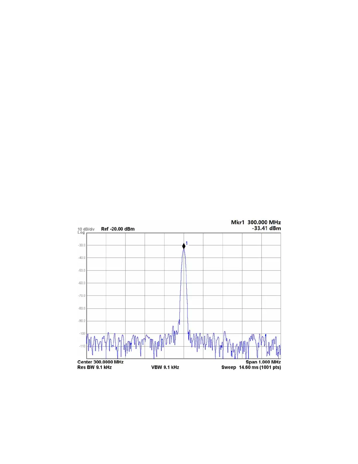
4. Tune the spectrum analyzer to 300 MHz with a span of 1 MHz
5. Measure the signal level using the peak search function of the spectrum
analyzer. The level of the 300 MHz signal should be -32.0 dBm, ±3.0 dB, as
shown in Figure 14-4.
Figure 14-4 Input Signal Level Verification
6. If the signal level measured is correct the input signal going to the A25
Wideband Analog IF assembly is of the correct level. If not, refer to
Chapter 8, “Front End Control” and determine why the signal level coming
from it is not correct.

 Loading...


