536 Keysight N9038A MXE Service Guide
Assembly Replacement Procedures
RF Area - Option 503, 508, & 526
RF Area - Option 503, 508, & 526
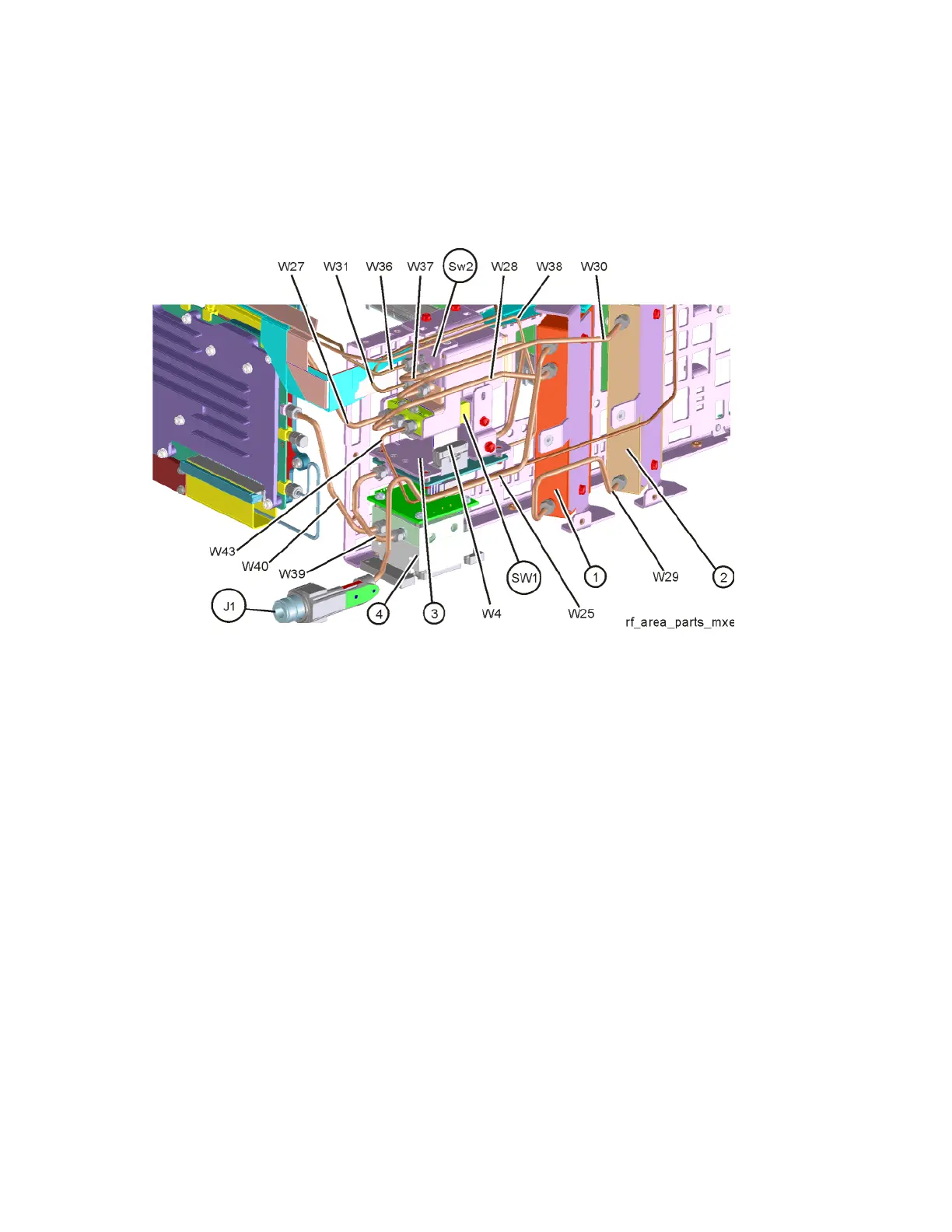
Refer to Figure 18-6. The RF area consists of RF attenuator A (1), RF
attenuator B (2), RF Switch/High Band Preamp assembly (3), and YTF (4).
Figure 18-6 RF Area Components and Cables - Option 503, 508, & 526
To gain access to the attenuators, RF Switch/High Band Preamp assembly, or
YTF for removal, follow these steps:
1. Remove the instrument outer case. Refer to the Instrument Outer Case
removal procedure.
2. Remove the front panel. Refer to the Front Frame Assembly removal
procedure.
3. Remove the top brace. Refer to the Top Brace and Power Supply Bracket
removal procedure.
4. Refer to Figure 18-7. Remove the Chassis Right Side Outer bracket (1) by
removing the eleven screws (2) (0515-0372) using the T-10 driver.

 Loading...


