2-70 Service Manual
5026
6
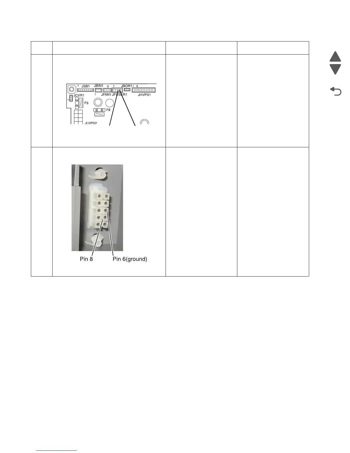
1. POR the printer.
2. Place a voltmeter between pin 8 and pin 6
(ground) on the JFUSER1 connector on
the system board.
3. Does the meter read +5 V dc?
Go to step 7. Replace the system board.
See “System board
removal” on page 4-163.
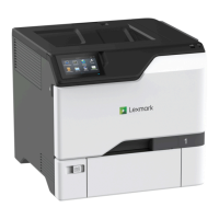
7
Place a voltmeter between the fuser
autoconnect pin 8 and ground (6).
Does the meter read +5 V dc?
Go to step 8. Replace the fuser DC
cable. See “Fuser DC
cable removal” on
page 4-121.
Step Questions / actions Yes No