4-214 Service Manual
5026
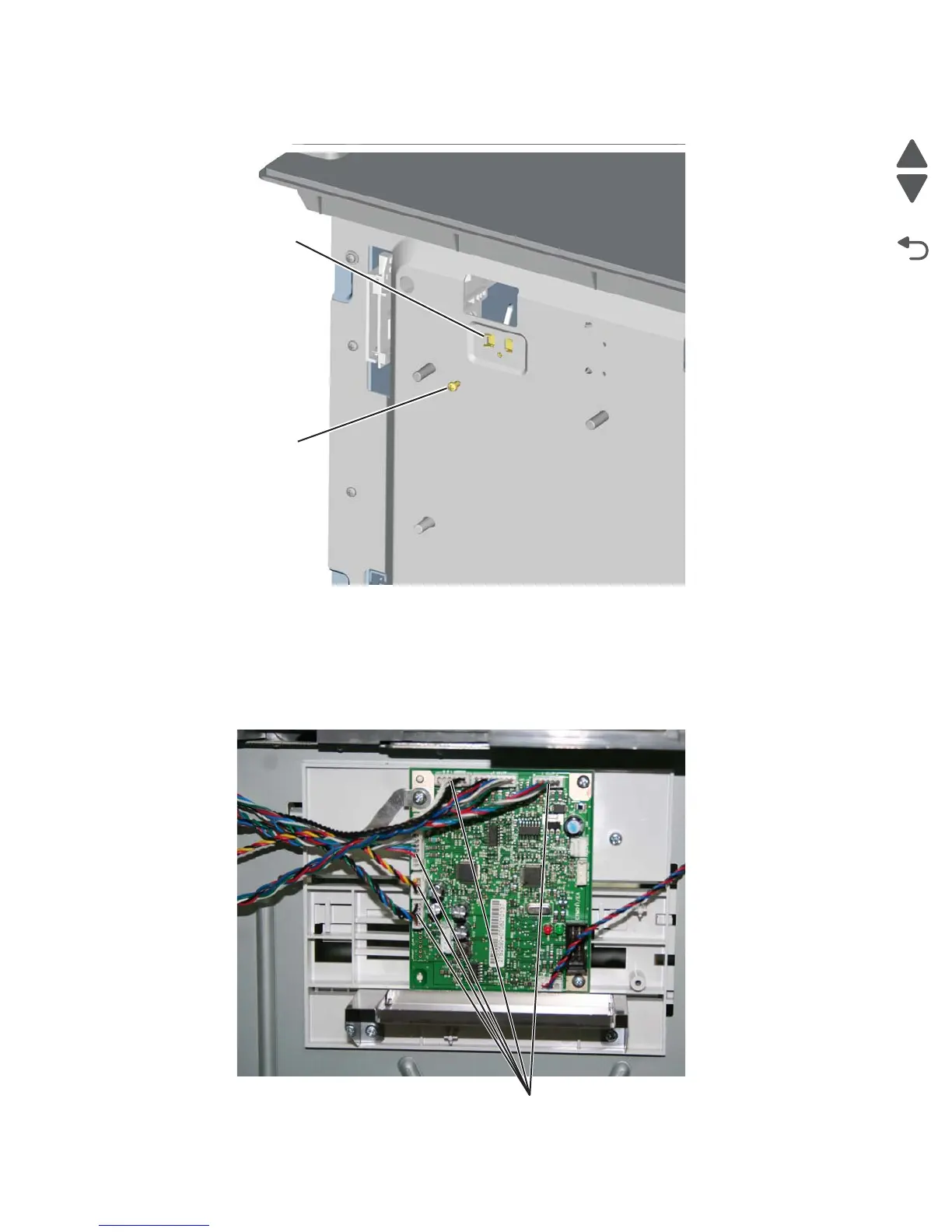
4. Remove the screw (C) securing the sensor to the rear frame, and then release the hooks (D).
Note: Remove the cable from the restraint, and observe the routing for reinstallation.
5. Remove the photo interrupter sensor with cable assembly.
Top plate assembly removal
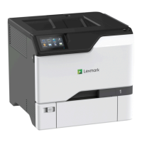
1. Remove the high-capacity input tray (HCIT) right cover. See “HCIT right cover removal” on page 4-204.
2. Disconnect the five connectors (A) from the HCIT controller board.