Repair information 4-3
5026
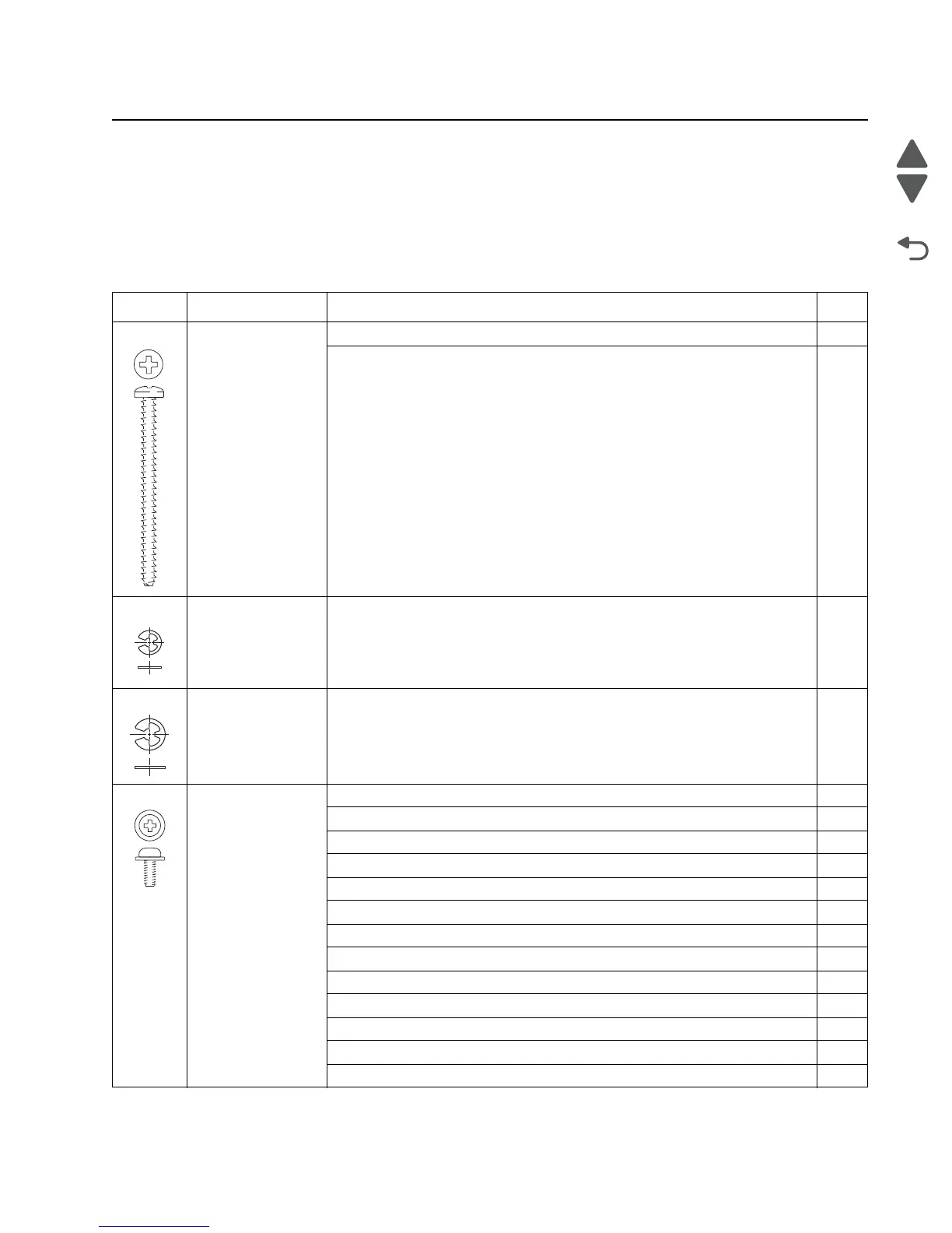
Screw and retainer identification table
The following table contains screw types and retainers, locations, and quantities necessary to service the
printer. Pay careful attention to each screw type location when doing removals. You must install the correct
screw type in each location during reassembly.
Sizes are as close to actual as possible, as long as the printout is not scaled or resized.
Screw identification table
P/N Screw type Location Qty
10B1580 #6 panhead Cartridge cooling fan to top cover 2
Cooling fan to top cover 2
1126828 E-clip M3 LR overcenter bell crank to side frame 1
1126829 E-ring M4 MP feeder gears to right side frame studs 2
18B0832 Taptite M3 L6
panhead
5 V interlock switch to right frame 1
Card support plate to upper plate 2
Card support plate to lower plate 3
Card support plate (and printhead ground) to left frame 5
Card support plate to right frame 4
Cartridge left guide assembly to left plate (interior side of plate assembly) 4
COD (color-on-demand) drive assembly to upper plate 3
COD shaft assembly to upper plate 2
Contacts assembly to left frame next to auger worm gear 2
Contacts assembly to left frame near duct 2
EP drive to right plate (exterior side) 8
Front door ground wire to right frame bracket 1
HVPS to left frame plate 1