4-54 Service Manual
5026
Top access cover assembly removal
See “Top access cover assembly, 2.3 inch” on page 7-3 for the part number.
Warning: When replacing any one of the following components:
• Operator panel assembly
• System board
• Top access cover assembly
Only replace one component at a time. Replace the required component, and perform a POR before
replacing a second component listed above. If this procedure is not followed, the printer will be
rendered inoperable.
1. Remove the rear frame cover. See “Rear frame cover removal” on page 4-47.
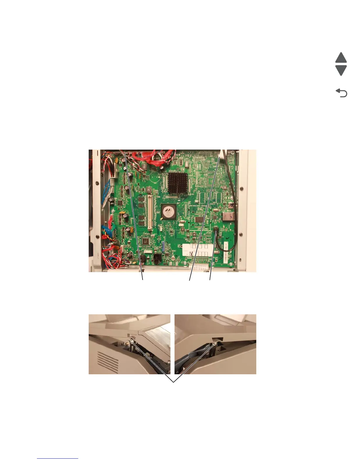
2. Disconnect the cable connectors at operator panel connector (A), JFMUSB1 (B), and JBIN1 (C) on the
system board.
3. Remove the rear upper cover. See “Rear upper cover removal” on page 4-50.
4. Open the front access cover and top access cover
5. Remove the two screws (D), one on either side of the printer, that connects the links.