2-124 Service Manual
5026
24 V interlock switch service check
Step Questions / actions Yes No
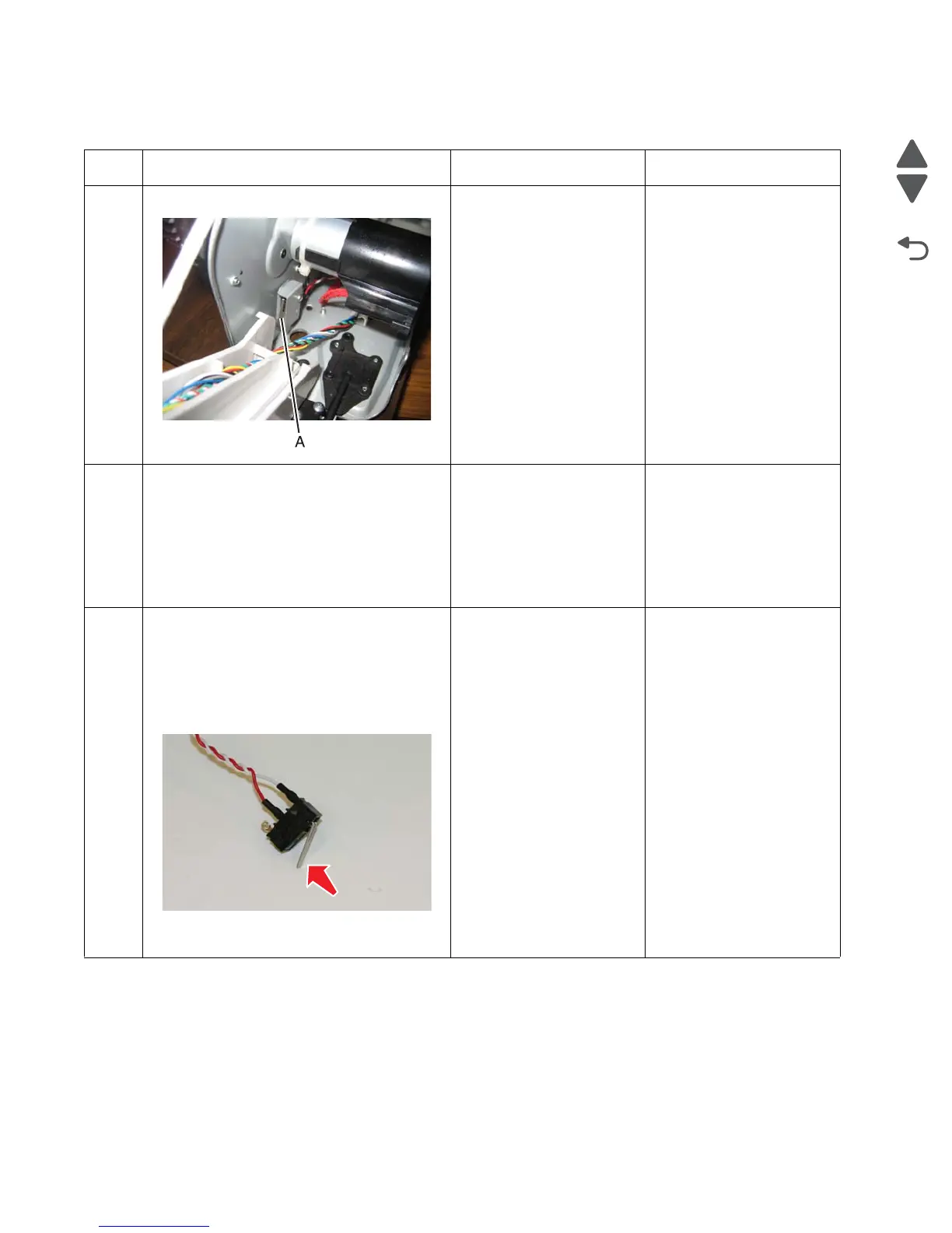
1 Is the 24 V interlock switch damaged? Replace the 24 V interlock
switch. See “24 V
interlock switch removal”
on page 4-63.
Go to step 2.
2
Turn the printer off, and remove the rear
frame cover. See “Rear frame cover
removal” on page 4-47.
Check the cable in connector JCVR1 for
proper connection to the system board, for
pinch points, and for any other damage to the
cable or connector.
Is the cable damaged?
Replace the 24 V interlock
switch. See “24 V
interlock switch removal”
on page 4-63.
Go to step 3.
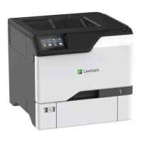
3
1. Disconnect the cable in connector JCVR1.
2. Connect the new 24 V interlock switch to
the connector JCVR1.
3. Bring the printer up in Diagnostics Menu
(turn off the printer, press and hold
buttons 3 and 6, then turn on the printer).
4. Activate the new 24 V interlock switch.
Does the display change from Close Front
Door to the Diagnostic Menu.
Replace the 24 V interlock
switch. See “24 V
interlock switch removal”
on page 4-63.
Replace the system board.
See “System board
removal” on page 4-163.