Diagnostic information 2-103
5026
920.08—Exit sensor service check
Step Questions / actions Yes No
1 Verify the paper is loaded properly in the
paper tray or manual feed slot.
Is the paper properly loaded?
Go to step 2. Load paper correctly.
2
1. Turn the printer off.
2. Install the new fuser. See “Fuser
removal” on page 4-118
Note: Do not reset fuser count or run
motor calibration yet.
3. POR the printer.
Did the error clear?
Problem resolved.
Note: Complete the fuser
installation: reset fuser
count and run motor
calibration. See “Fuser
removal” on page 4-118.
Remove the new fuser, and
go to step 3.
3
Remove the rear frame cover. See “Rear
frame cover removal” on page 4-47.
Check the fuser DC cable in the connector
JFUSER1 for proper connection to the system
board, for pinch points, and for any other
damage to the cable or the connector.
Is the cable damaged?
Replace the fuser DC
cable. See “Fuser DC
cable removal” on
page 4-121.
Go to step 4.
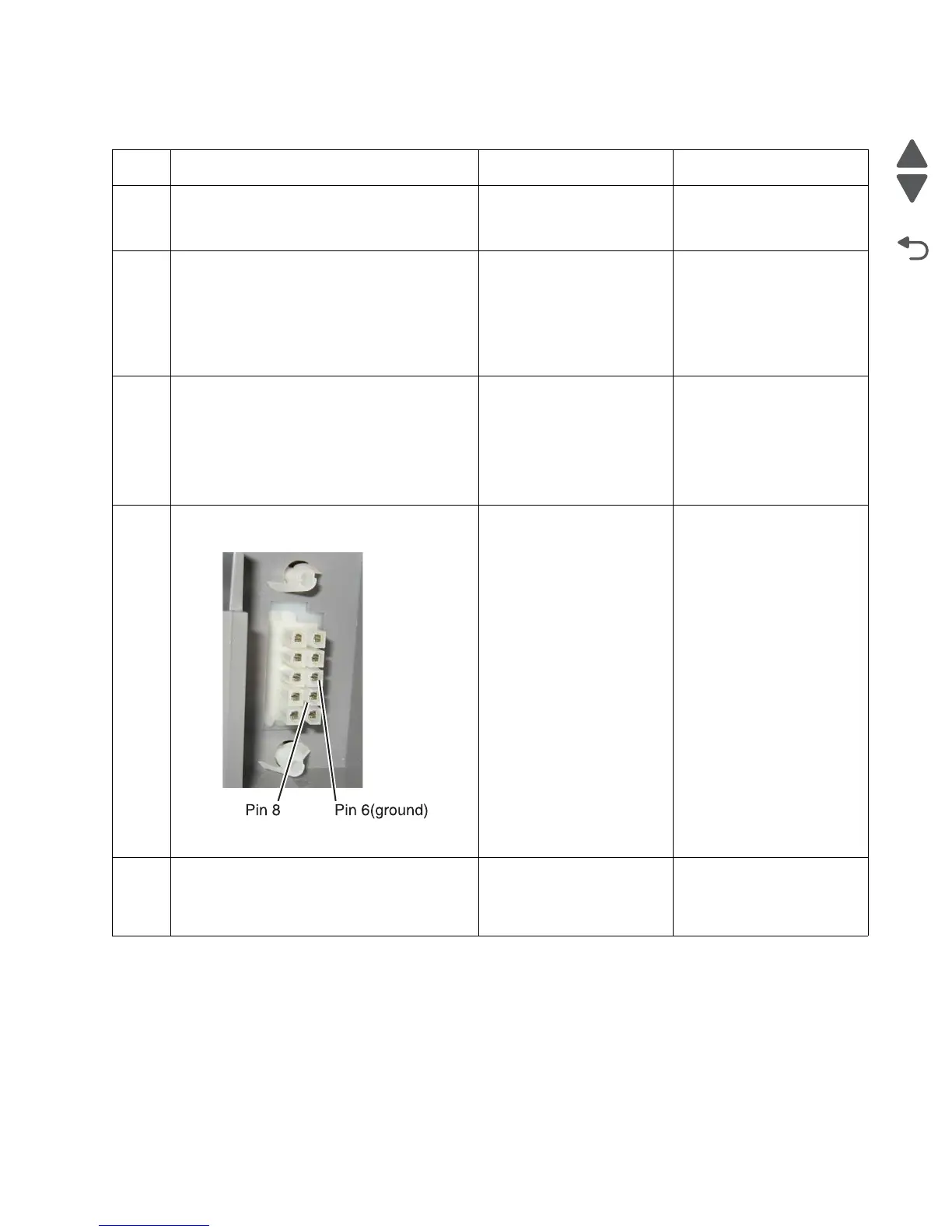
4
Place a voltmeter between the fuser DC
autoconnect pin 8 and ground (pin 6).
Does the meter rear +5 V dc?
Go to step 6. Go to step 5.
5
Place a voltmeter between the connector
JFUSER1 pin 8 and ground (pin 6) on the
system board.
Does the meter read +5 V dc?
Go to step 6. Replace the fuser DC
cable. See “Fuser DC
cable removal” on
page 4-121.