2-48 Service Manual
5026
4
Remove the rear frame cover. See“Rear
frame cover removal” on page 4-47. Check
the cable in connector JFUSER1 (fuser DC
cable) for proper connection to the system
board, the cable for pinch points, and the
cable or connector for any other damage.
Is the cable damaged?
Replace the fuser DC
cable.See “Fuser DC
cable removal” on
page 4-121.
Go to step 5.
5
Check the cable in connector JLVPS2 for
proper connection to the system board, the
cable for pinch points, and the cable or
connector for any other damage.
Is the cable damaged?
Replace the LVPS. See
“Low-voltage power
supply (LVPS) removal”
on page 4-127.
Go to step 6.
6
Measure the continuity across all of the fuses
on the system board.
Are any of the fuses blown?
Replace the system board.
See “System board
removal” on page 4-163.
Go to step 7.
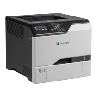
7
Check for the following continuity between the
DC autoconnect JFUSER1 on the system
board.
Is continuity present?
Go to step 8. Replace the fuser DC
cable. See “Fuser DC
cable removal” on
page 4-121.
8
Check for continuity between the following
pins of the AC autoconnect and the pins of
the connector that connects to the LVPS.
Is continuity present?
Replace the system board.
See “System board
removal” on page 4-163.
Replace the fuser AC
cable. See “Fuser AC
cable removal” on
page 4-120.
Step Questions / actions Yes No
DC auto-
connect
JFUSER1
Pin 9 Pin 9
Pin 10 Pin 10
LVPS
connect
AC Auto-
connect
Pin 1 Pin 5
Pin 3 Pin 1