Issue 5 November 2000
363-206-208
Powering, Verification, and Circuit Pack Installation for the DDM-2000 OC-12 Multiplexer
Lucent Technologies - Proprietary
See Notice on first page
Notes:
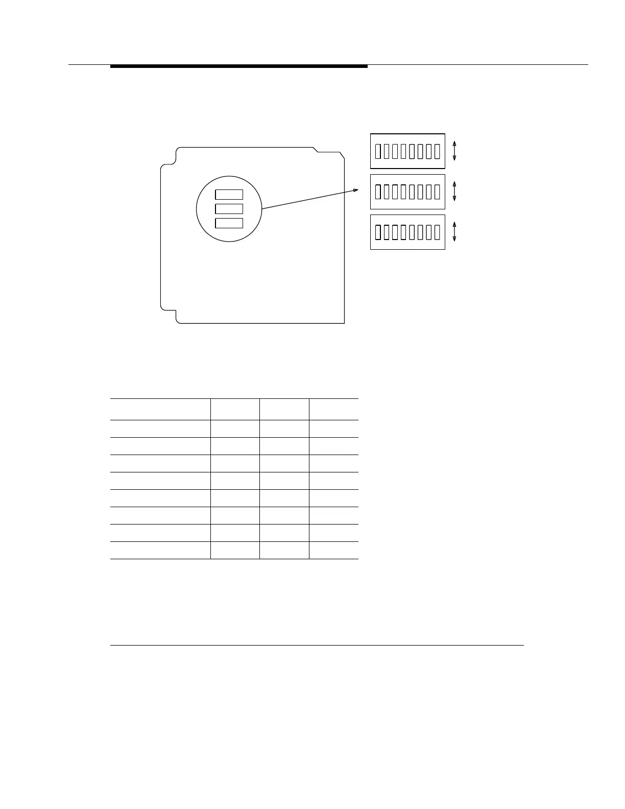
1. If an invalid setting is selected, the fault LED lights and an alarm is generated.
2. Switch S1 sets the network element number of the shelf. The network element number and the site ID num-
ber form a unique address for a shelf at a site. Obtain the network element number from the customer.
3. Switch 1, sections 4, 5, 6, 7, and 8 must be to the ON position.
Figure 5-5. BCP1 OHCTL Option Switches (Sheet 1 of 2)
Switch 1 Settings
Network Element Sec 1 Sec 2 Sec 3
1 ONONON
2OFFONON
3ONOFFON
4OFFOFFON
5 ONONOFF
(Invalid) OFF ON OFF
(Invalid) ON OFF OFF
(Invalid) OFF OFF OFF
OFF
ON
87654
OFF
ON
87654
OFF
ON
87654
S3
S1
S2
ON
321
ON
321
ON
321
Connector
Edge
S3
S1
Component Side
S2