Issue 5 November 2000
363-206-208
Equipment and Front Access Cable Installation for the DDM-2000 OC-12 Multiplexer
Lucent Technologies - Proprietary
See Notice on first page
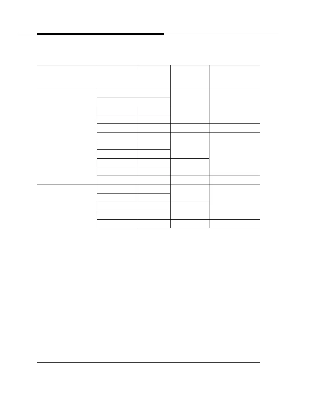
Table 3-1 DS3 Cable Assemblies
Description (Note 1)
ED-8C724-20
Group
Cable
Length (ft.)
(Note 2)
Cable Type
(Note 3)
Other End
Connector (Note 4)
To DSX-3
or
FT-2000
OC-48†
335 (D.A.)* 150 1735006A
KS-23558,L6 BNC
336 (D.A.)* 250 (max.)
333 (D.A.)* 150 735A
334 (D.A.)* 250 (max.)
338 150 KS-19224, L2 KS-23558,L4 BNC
337 450 (max.) 734A/735A KS-23558,L5 BNC
To DACS III-2000
330 (D.A.)* 150 1735006A
9821AE
331 (D.A.)* 500 (max.)
328 (D.A.)* 150 735A
329 (D.A.)* 500 (max.)
332 (D.A.)* 900 (max.) 734A/735A ‡
To DACS IV-2000
325 (D.A.)* 150 1735006A
9821EA &
9821FA
326 (D.A.)* 500 (max.)
323 (D.A.)* 150 735A
324 (D.A.)* 500 (max.)
327 (D.A.)* 900 (max.) 734A/735A **
Table 3-1 Notes:
1. All the DS3 cable assemblies can be used for any muldem. DDM-2000 OC-12 DS3 backplane connectors
are J30-J35 (for muldem A), J36-J41 (for muldem B), J42-J47 (for muldem C), and J48-J53 (for muldem
D).
2. Cable lengths are specified by the customer for all cables designated as having a max. length. All other
cable lengths are fixed.
3. A 1735006A six conductor cable provides three DS3 IN and three DS3 OUT cables to accommodate one
full muldem on the DDM-2000 OC-12 shelf. 734A, 735A, and KS-19224, L2 cables provide one DS3 IN
cable and one DS3 OUT cable to accommodate a partially equipped muldem.
4. All the Group 323 to 338 cables have a BNC KS-23626, L6 connector on one end except Group 338 which
has a BNC KS-23626, L4 connector on one end.
* Discontinued Availability (D.A.) means cable can no longer ordered.
† for cables going to DACS III-2000 and DACS IV-2000 equipped with a BNC I/O panel, cable lengths desig-
nated as 250 (max.) and 450 (max.) become 500 (max.) and 900 (max.) respectively.
‡ The Group 332 cable consists of two 734A cables (1-900 feet) with a BNC connector on one end and no
connector on the other end. This group also includes two 13-foot 735A cables with a 219P connector on
one end and an ED-7G001-23, Group 204 cable assembly on the other end. The 735A cable will have to
be spliced to the 734A cable per the 219P connector.
** The Group 327 cable consists of two 734A cables (1-900 feet) with a BNC connector on one end and no
connector on the other end. This group also includes two 13-foot 735A cables with a 219P connector on
one end and a 9821EA or 9821FA connector on the other end. The 735A cable will have to be spliced to
the 734A cable per the 219P connector.