HOISTS 2250 SERVICE/MAINTENANCE MANUAL
5-18
Published 07-19-16, Control # 249-01
5. Inspect all pins and linkage for excessive wear and
replace parts as required. Excessively worn pins and
linkage make it difficult to properly adjust the clutches.
6. Lubricate the clutch linkage. See Lubrication
Section 9
for more information.
7. Position the rod end (18) of the air cylinder (13) in the
access hole.
The dimension between the end of the cylinder and the
rod end must be 38 to 54 mm (1-1/2 to 2-1/4 in).
Proceed as follows:
• If the dimension is within the specified range, no
further adjustment is required. Go to step 10
.
• Perform step 8
through step 10 when the minimum
dimension is reached.
8. When the dimension reaches 38 mm (1-1/2 in), proceed
as follows.
a. Position the adjusting nut (7) in the access hole.
b. Loosen the jam nut (6) several turns.
c. Release the clutch. See the procedure in Table 5-1
.
d. Tighten the adjusting nut as required. Turning the
adjusting nut one flat moves the cylinder rod (17)
out approximately 14 mm (9/16 in).
e. Apply the clutch. See the procedure in Table 5-1
.
f. Repeat step 7
and step 8a through step 8e until the
dimension is 54 mm (2-1/8 in).
g. Repeat step 8
a and securely tighten the jam nut to
lock the adjustment.
9. Adjust each band guide (11) as follows.
a. Position the band guide in the access hole.
b. With the clutch applied, check the clearance
between the band guide and clutch band with a
feeler gauge. Clearance should be 1 mm (1/32 in).
c. If necessary, loosen the mounting screws and
reposition the band guide to obtain the specified
clearance. Then securely tighten the mounting
screws.
10. Reinstall the cover over the access hole.
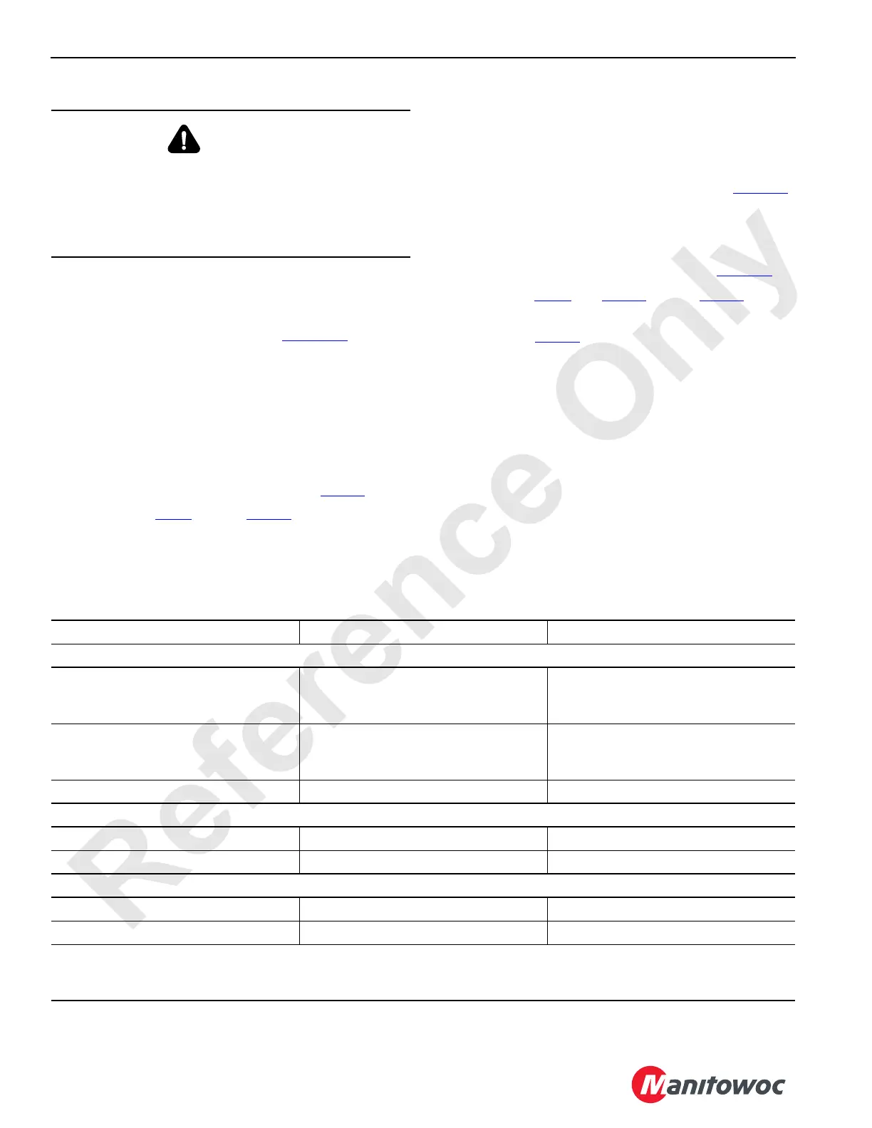
Table 5-1. Clutch Inspection
WARNING
Falling Load Hazard!
Aftermarket clutch linings may not provide the proper
clutch torque. The clutch could slip, allowing the load to
drop, resulting in death or serious injury.
Only use Manitowoc Cranes original equipment linings.
Clutch Being Adjusted To Release Clutch To Apply Clutch
Three Drum Configuration
Left Rear
Select Left with Rear Drum Selector
Switch
Pull back the front drum handle. Pull back the rear drum handle.
Right Rear
Select Right with Rear Drum Selector
Switch
Pull back the front drum handle. Pull back the rear drum handle.
Front Pull back the rear drum handle. Pull back the front drum handle.
Two Drum Split Rear Configuration
Left Rear Pull back the right drum handle. Pull back the left drum handle.
Right Rear Pull back the left drum handle. Pull back the right drum handle.
Two Drum Independent Configuration
Front Pull back the rear drum handle. Pull back the front drum handle.
Rear Pull back the front drum handle. Pull back the rear drum handle.
NOTE: Pull back the specified handle only enough to release and apply the clutch without turning the drum. Listen for
exhausting air from the air cylinder. Air exhausts from the cylinder on the clutch being serviced when the clutch
applies. Air exhausts from the cylinder on the opposite clutch when the clutch being serviced releases.
 Loading...


