MASSO
MASSO Documentation
11.25. MASSO G2 Drive and Relay wiring
INFORMATION: This describes the wiring of the A & B axis on the Masso G2. For wiring of the X,
Y & Z axis on the Masso G2 refer to examples in the G3 Section of this documentation.
WARNING: Axis Step and Direction signals are common Ground and precautions must be taken to
wire the controller to avoid any electrical damage to the system:
All axis outputs are common Gnd with +4 voltage signals.
Never short-circuit the signals with each other or any other voltage.
All signals must be isolated to other signals and connected directly to the drives
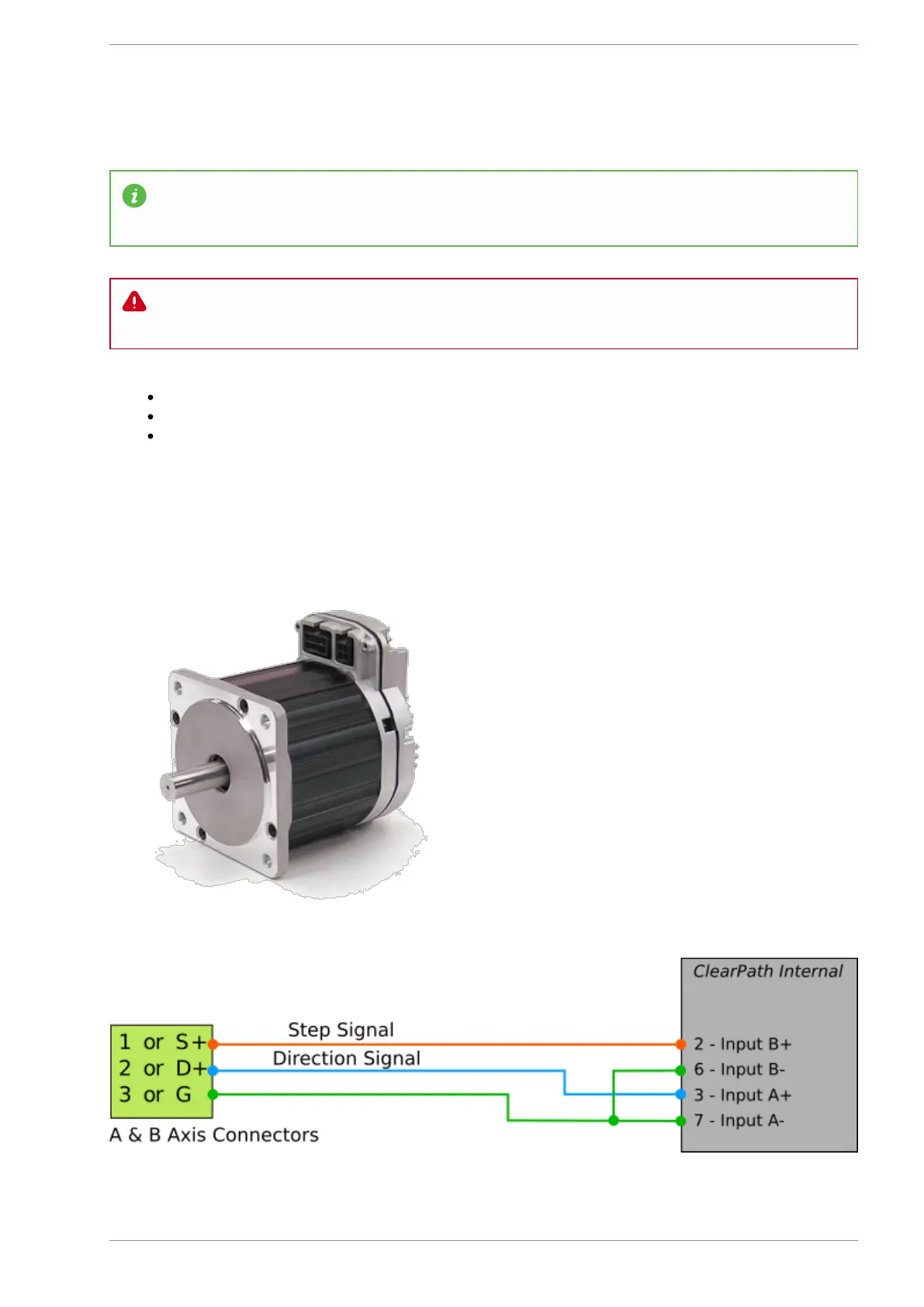
MASSO G2 A & B axis wiring examples
Teknic - ClearPath wiring
v5.18 - 08 Apr,2021
www.masso.com.au Page 362 of 477