8.3 PLC Side Setting
8.3.3 Connecting to Ethernet module (A Series)
8 - 35
1
OVERVIEW
2
BUS CONNECTION
3
DIRECT CONNECTION
TO CPU
4
COMPUTER LINK
CONNECTION
5
MELSECNET/10
CONNECTION (PLC TO
PLC NETWORK)
6
CC-Link CONNECTION
(INTELLIGENT DEVICE
STATION)
7
CC-Link CONNECTION
(Via G4)
8
ETHERNET
CONNECTION
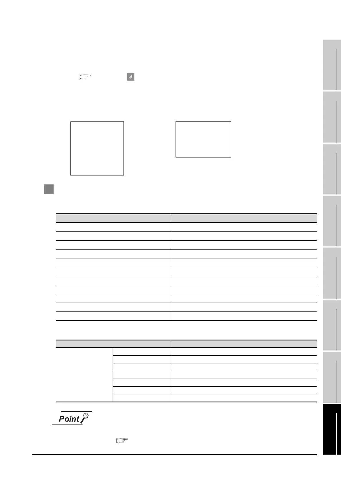
(3) Communication confirmation
The RDY LED on the Ethernet module turn on when the module is ready to communicate.
For confirming the communication state, refer to the following.
Section 8.3.1 Confirming the communication state of Ethernet module
The BUF1 LED turns on when the opening processing of the connection No. 1 is completed in
normal at executing of the sequence program example described at (2).
4 [Communication settings] and [Ethernet setting] of GT Designer2
(1) Communication settings
(2) Ethernet setting
[Communication Settings], [Ethernet] of GT Designer2
For [Communication Settings], [Ethernet] of GT Designer2, refer to the following.
Section 8.2.3 Setting communication interface (Communication settings)
Item Setting(Use default value.)
GOT NET No. 1
GOT PC No. 1
GOT IP Address 192.168.0.18
GOT Port No. (QJ71E71/AJ71(Q)E71) 5001
GOT Port No. (Ethernet Download) 5014
Default Gateway 0.0.0.0
Subnet Mask 255.255.255.0
Retry 3 Times
Startup Time 3 sec
Timeout Time 3 sec
Delay Time 0 ms
Item Setting
Ethernet setting No.1
Host *
N/W No. 1
PLC No. 2
Type AJ71E71
IP address 192.168.0.19
Port No. 5001
Communication UDP(fixed)
RUN BUF1
BUF2
BUF3
BUF4
BUF5
BUF6
BUF7
BUF8
RDY
BSY
SW.ERR.
COM.ERR.
CPU R/W
TEST
TEST ERR.
BSY
SW.ERR.
COM.ERR.
CPU R/W
TEST ERR.
TEST
RDY
RUN BUF1
BUF2
BUF3
BUF4
BUF5
BUF6
BUF7
BUF8
A1SJ71E71N3-T, A1SJ71E71N-B5, A1SJ71E71N-B2,
A1SJ71E71N-T, A1SJ71E71N-B5T,
A1SJ71E71-B5-S3, A1SJ71E71-B2-S3
J71E71N3-T, AJ71E71N-B5, AJ71E71N-B2,
J71E71N-T, AJ71E71N-B5T,
J71E71-S3

 Loading...


