23 - 12
23.2 Connection Cable
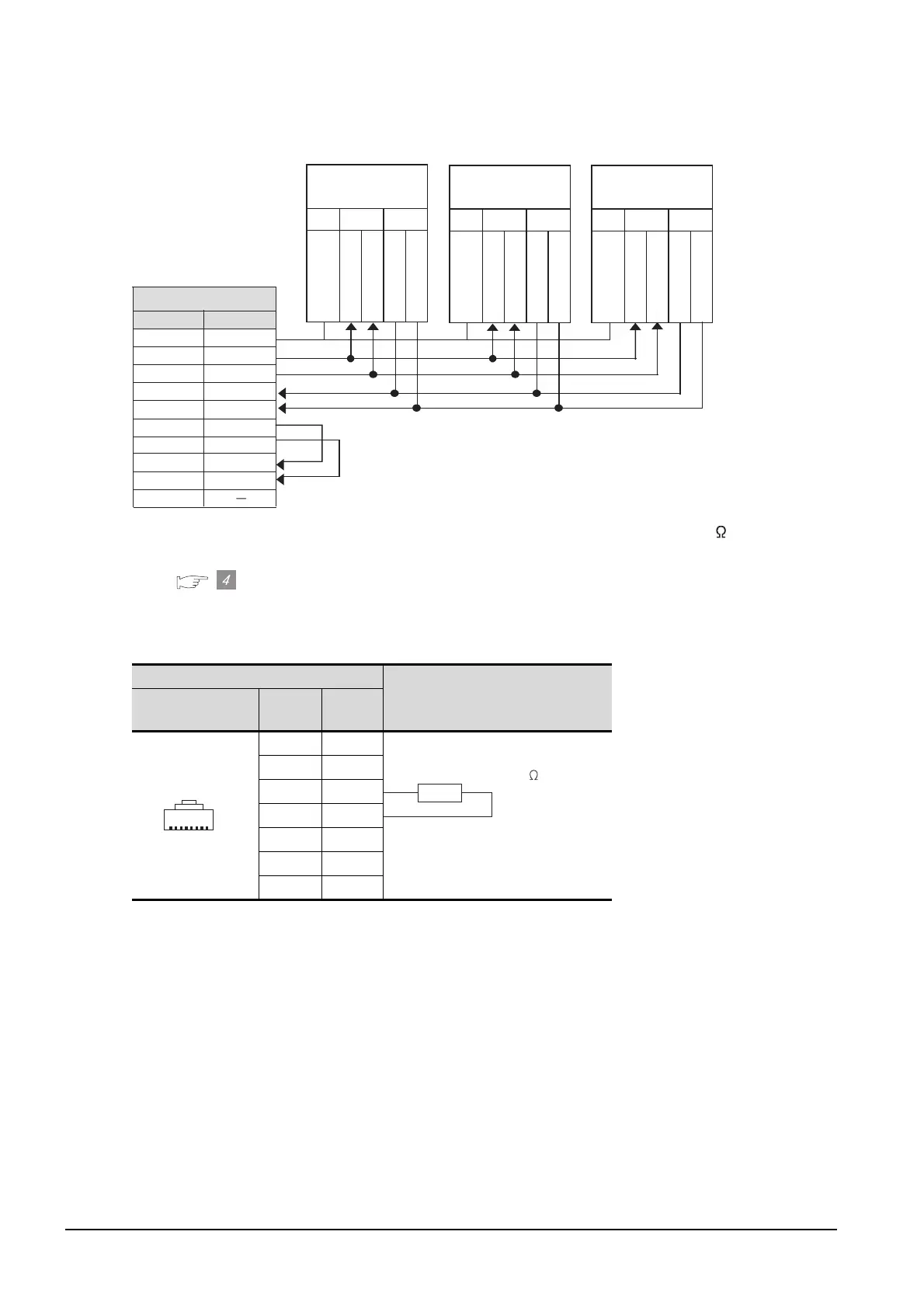
(6) RS-422 cable 6)
• Set the terminator switch built in the farthest inverter from the GOT to ON (100 ).
• Set the terminating resistor of GOT side, which will be a terminal, to “Enable”.
Connecting terminating resistors
(7) RS-422 cable 7)
*1 The connector figure shows the engagement face.
Distributor side
Cable connection and signal direction
Pin layout
*1
Signal
name
Pin No.
SDA 5
SDB 4
RDA 3
RDB 6
P5S 2
P5S 8
SG 1
SG
5
SDB
6
SDA 1
RDB 7
RDA 2
RSA 3
RSB 8
CSA 4
CSB 9
FG
VCC
RXD TXD
R
X
D
1
+
G
N
D
R
X
D
1
-
T
X
D
1
+
T
X
D
1
-
VCC RXD TXD
R
X
D
1
+
G
N
D
R
X
D
1
-
T
X
D
1
+
T
X
D
1
-
Station No.0
Station No.1
Signal name
Pin No.
GOT side
RS485 terminall block
(built into the inverter)
RS485 terminall block
(built into the inverter)
VCC
RXD TXD
R
X
D
1
+
G
N
D
R
X
D
1
-
T
X
D
1
+
T
X
D
1
-
Station No.n
RS485 terminall block
(built into the inverter)
PU port
1
8
PJ-45 plug (male)
Terminating resistor 100
1/2W

 Loading...


