24.2 Connection Cable
24.2.1 RS-232 cable
24 - 9
17
CONNECTION TO
ALLEN-BRADLEY PLC
18
CONNECTION TO
SIEMENS PLC
19
MICROCOMPUTER
CONNECTION
20
CONNECTION TO OMRON
TEMPERATURE
CONTROLLER
21
CONNECTION TO
YAMATAKE TEMPERATURE
CONTROLLER
22
CONNECTION TO RKC
TEMPERATURE
CONTROLLER
23
CONNECTION TO
FREQROL SERIES
INVERTER
24
SERVO AMPLIFIER
CONNECTION
24.2 Connection Cable
The RS-232 cable or RS-422 cable used for connecting the GOT to the servo amplifier should be prepared
by the user.
The following provides connection diagrams for each cable, connector specifications and other information.
24.2.1 RS-232 cable
The following shows the connection diagrams and connector specifications of the RS-232 cable used for
connecting the GOT to a servo amplifier.
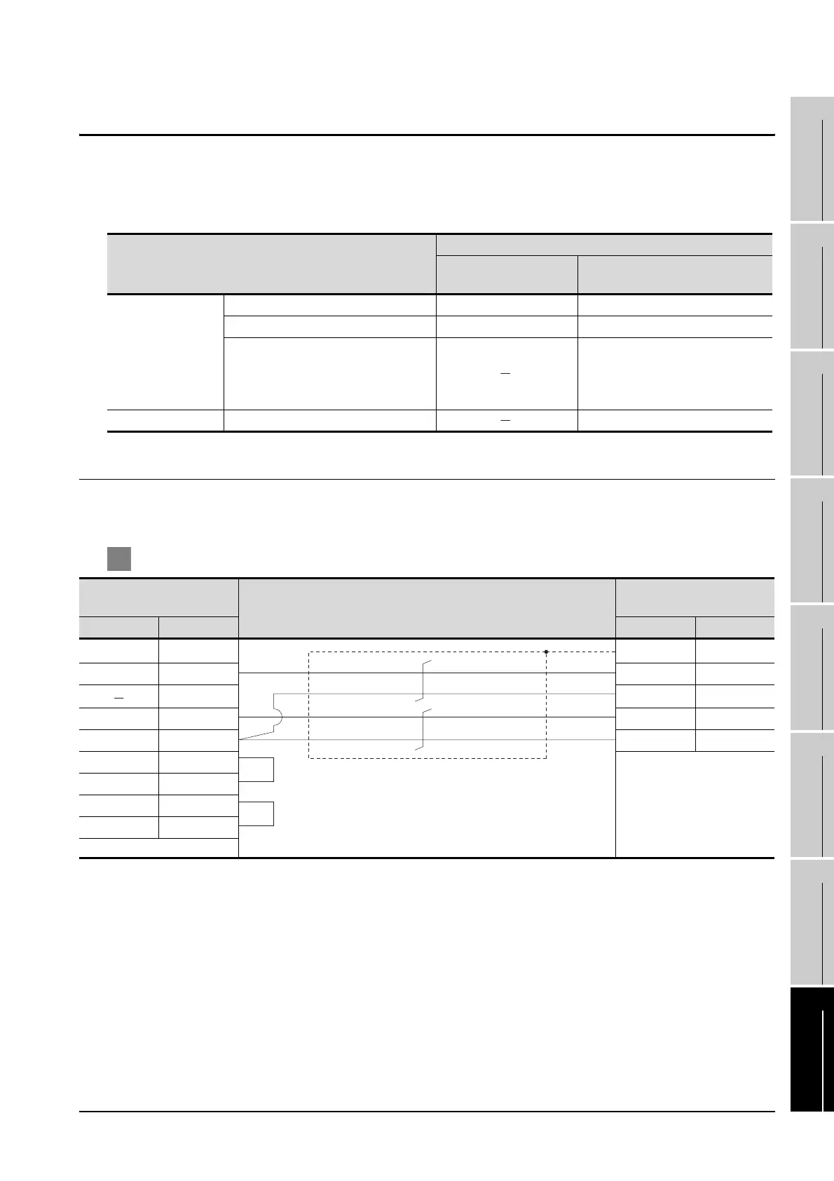
1 Connection diagram
*1 GT15 : CD, GT11 : NC
Series and model names
connection cable
RS-232 cable
(Refer to section 24.21)
RS-422 cable
(Refer to section 24.22)
servo amplifier
MELSERVO-J2-Super Series RS-232 cable 1) RS-422 cable 1)
MELSERVO-J2M Series RS-232 cable 1) RS-422 cable 1)
MELSERVO-J3 Series
RS-422 cable 3)
RS-422 cable 4)
RS-422 cable 5)
RS-422 cable 6)
Distributor BMJ-8 RS-422 cable 4)
GOT side
Cable connection and signal direction
Connector for interface unit's or
servo amplifier's CN3
Signal name Pin No. Pin No. Signal name
CD/NC
*1
1 Plate FG
SD(TXD) 3 2RXD
9 11 LG
RD(RXD) 2 12 TXD
SG 5 11 LG
RS(RTS) 7
CS(CTS) 8
DR(DSR) 6
ER(DTR) 4
 Loading...


