670
11 POSITIONING INSTRUCTION
11.1 Positioning Instruction
DDRVI [For the FX5 Series operand specification]
This instruction executes one-speed positioning by incremental drive.
■Descriptions, ranges, and data types
■Applicable devices
*1 T, ST, C cannot be used.
This instruction executes one-speed positioning by incremental drive. Specify the positioning address in the incremental
system, in which the transfer direction and transfer distance from the current position (relative address) are specified for
positioning.
• For (s1), specify the relative positioning address in user units. (The address must be within the range of -2147483647 to
+2147483647 number of pulses.)
• For (s2), specify the command speed in user units. (The speed must be 200 Kpps or lower in frequency.)
• For (d1), specify the axis number from which pulses are output.
• For (d2), specify the bit device of the normal complete flag or abnormal end flag for the DDRVI instruction.
For details on the function and error code, refer to Built-in positioning manual.
Two devices are occupied from the device specified in (d2). Make sure that these devices are not used in other controls.
For other precautions, refer to Built-in positioning manual.
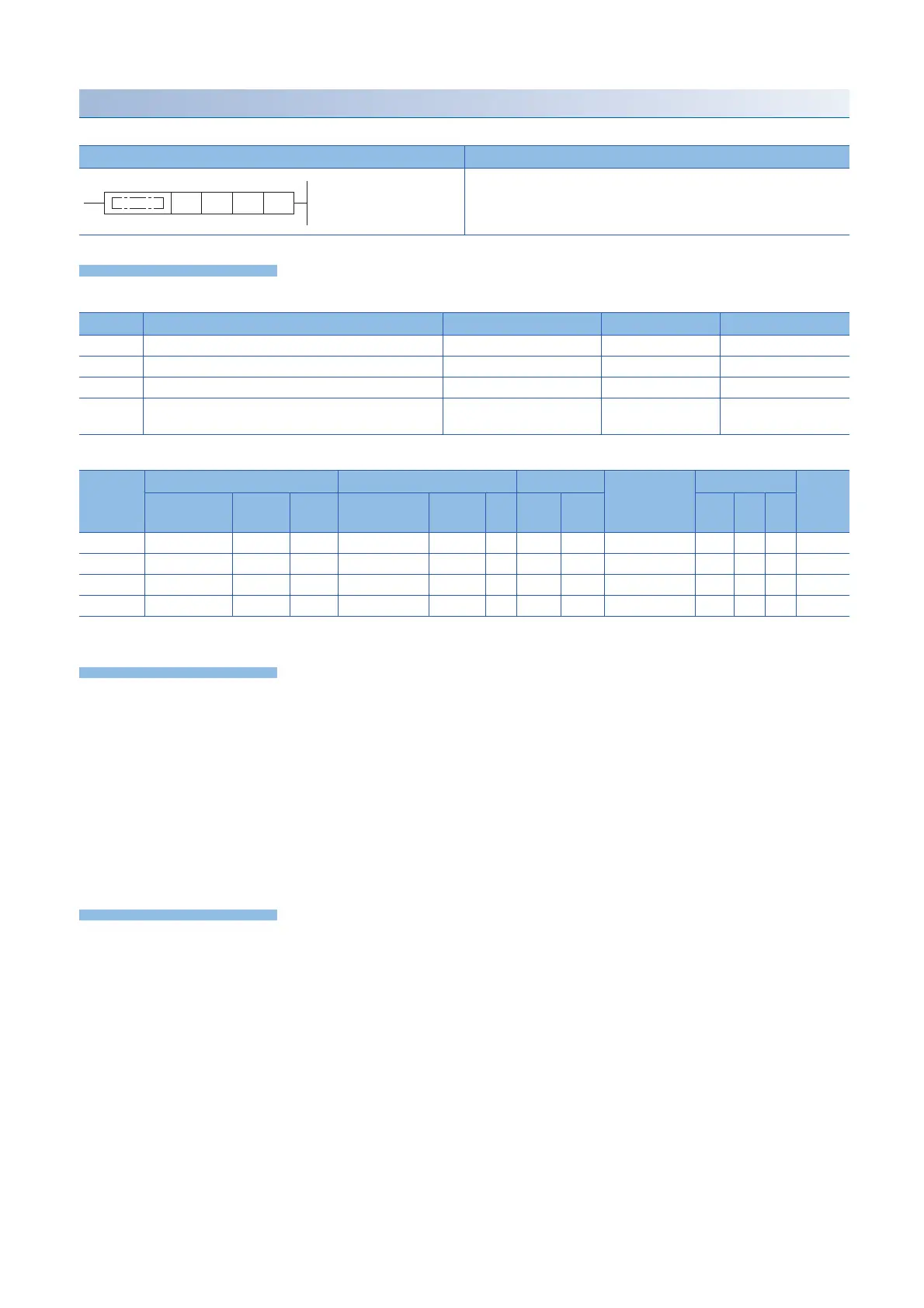
Ladder diagram Structured text
ENO:=DDRVI(EN,s1,s2,d1,d2);
Operand Description Range Data type Data type (label)
(s1) Positioning address -2147483648 to +2147483647 32-bit signed binary ANY32
(s2) Command speed 1 to 2147483647 32-bit signed binary ANY32
(d1) Axis number from which pulses are to be output K1 to 4 16-bit signed binary ANY_ELEMENTARY
(d2) Bit device number of the positioning complete flag or
abnormal end flag
Bit ANY_BOOL
Operand Bit Word Double word Indirect
specification
Constant Others
X, Y, M, L,
SM, F, B, SB
U\G T, ST,
C, LC
T, ST, C, D,
W, SD, SW, R
U\G Z LC LZ K, H E $
(s1)
(s2)
(d1)
(d2)
*1
 Loading...

