4 Parts Replacement VJ-1604 Maintenance Manual
Rev.-05 4-60
4.5 Replacing Board Base Section (Y Rail Section)
This section describes the procedure to replace the boards in the Y rail section.
4.5.1 Replacing Heater Junction Board Assembly
• Before you replace a board assembly, remove the AC inlet cable.
You may suffer electric shock due to standby current.
• When you handle a circuit board, do not touch any elements on it with bare hands.
Doing so may cause electrostatic discharge and damage the elements.
1. Move the carriage to the opposite side of the origin.
"4.8.1 Releasing Head Lock" p.4-106
2. Remove the side top cover R.
"4.2.6 Removing Side Top Cover R" p.4-12
3. Remove the cartridge cover (upper).
"4.2.9 Removing Cartridge Cover (Upper)" p.4-17
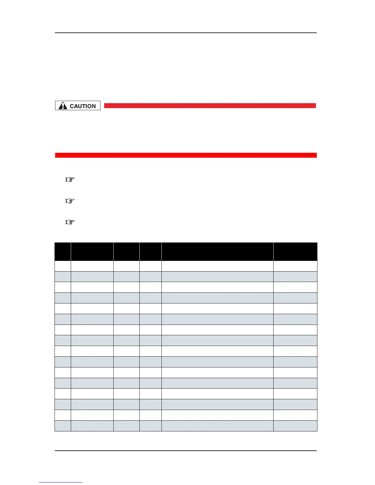
4. Detach the connector to the heater junction board assembly.
No. Connector No. # of
Pins
Color Connect to Remark
1 J1 Config CN
2 J2 4 White DC IN -> HEATER CONT (J8)
3 J3 Communication -> HEATER CONT (J9) LAN
4 J4 10 White HEATER CONT (J10) Option
5 J5 10 White INK SLOT1
6 J6 10 White INK SLOT2
7 J7 10 White INK SLOT3
8 J8 10 White INK SLOT4
9 J9 10 White Not in use
10 J10 10 White Not in use
11 J11 8 White SubTank1
12 J12 8 White SubTank2
13 J13 8 White SubTank3
14 J14 8 White SubTank4
15 J15 8 White Not in use
16 J16 8 White Not in use